Audi A4: Front Bumper
Overview - Bumper Cover
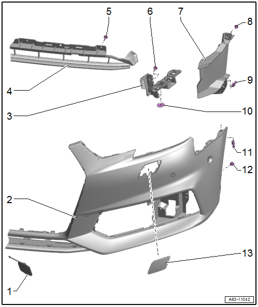
1 - Towing Eye Cover
2 - Bumper Cover
- Removing and installing. Refer to → Chapter "Bumper Cover, Removing and Installing".
- Adjusting. Refer to → Chapter "Bumper Cover, Adjusting".
- Overview - rear reflector. Refer to → Chapter "Overview - Rear Reflector"
- Overview - covers and air guides. Refer to → Chapter "Overview - Covers and Air Guides"
3 - Mount
- For the bumper cover
- Removing and installing. Refer to → Chapter "Bumper Cover Mount, Removing and Installing".
4 - Air Intake Grille
- Center
- Removing and installing. Refer to → Chapter "Air Intake Grille, Removing and Installing, Center".
5 - Bolt
- 2 Nm
- Quantity: 4
6 - Bolt
- 4 Nm
7 - Air Duct
- Side
- There are different versions. Refer to the Parts Catalog.
- Removing and installing. Refer to → Chapter "Side Air Duct, Removing and Installing".
8 - Bolt
- 2 Nm
- Quantity: 3
- S line quantity: 2
9 - Expanding Rivet
- Only S line
10 - Nut
- 4 Nm
- Quantity: 2
11 - Expanding Rivet
12 - Bolt
- 2 Nm
13 - Washer Nozzle Cover
- For the headlamp washer system
- Removing and installing. Refer to → Chapter "Headlamp Washer System Washer Nozzle Cover, Removing and Installing".
Overview - Rear Reflector
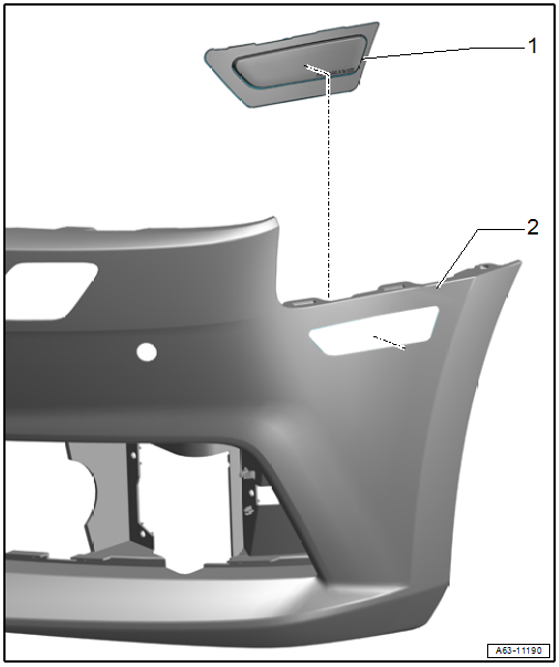
1 - Rear Reflector
- Removing and installing. Refer to → Chapter "Reflector, Removing and Installing".
2 - Bumper Cover
- Removing and installing. Refer to → Chapter "Bumper Cover, Removing and Installing".
Overview - Covers and Air Guides
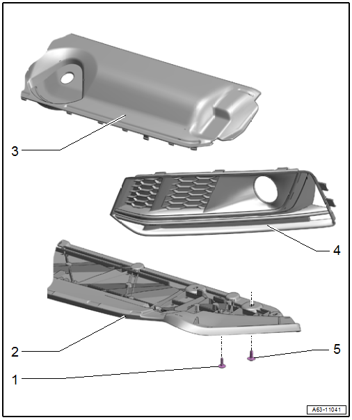
1 - Bolt
- 2 Nm
- Quantity: 4
2 - Bumper Cover End Plate
- There are different versions. Refer to the Parts Catalog.
- Removing and installing. Refer to → Chapter "Front Bumper Cover End Plate, Removing and Installing".
3 - Lock Carrier Cover
- Removing and installing. Refer to → Chapter "Lock Carrier Cover, Removing and Installing".
4 - Air Intake Grille
- Side
- There are different versions. Refer to the Parts Catalog.
- Removing and installing. Refer to → Chapter "Air Intake Grille, Removing and Installing, Side".
5 - Bolt
- 5 Nm
- Quantity: 5
Overview - Impact Member
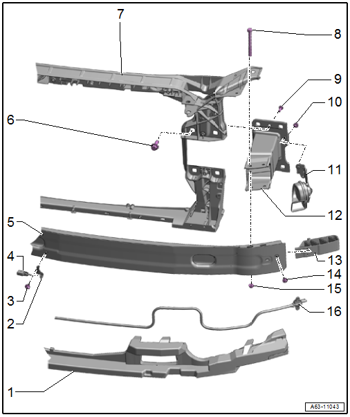
1 - Molded Foam Part
- Market-Specific Version
- Removing and installing. Refer to → Chapter "Molded Foam Part, Removing and Installing".
2 - Bracket
- For Outside Air Temperature Sensor -G17-
- There are different versions. Refer to the Parts Catalog.
3 - Bolt
- 2.5 Nm
4 - Outside Air Temperature Sensor -G17-
- Removing and installing. Refer to → Heating, Ventilation, and Air Conditioning; Rep. Gr.87; Additional Components for Control and Regulation; Outside Air Temperature SensorG17, Removing and Installing.
5 - Impact Member
- Removing and installing. Refer to → Chapter "Impact Member, Removing and Installing".
6 - Bolt
- 55 Nm
- Quantity: 4
7 - Lock Carrier
8 - Bolt
- Quantity: 2
- Tightening specification → Fig. "Front Impact Member - Tightening Specification and Sequence".
9 - Bolt
- 14 Nm
- For securing the impact member to the lock carrier
- Quantity: 2
10 - Nut
- Tightening specification. Refer to → Electrical Equipment; Rep. Gr.90; Horn; Overview - Horn.
11 - Bracket with Horn
- Removing and installing. Refer to → Electrical Equipment; Rep. Gr.90; Horn; High Tone HornH2/Low Tone HornH7, Removing and Installing.
12 - Impact Member Mount
- Removing and installing. Refer to → Chapter "Impact Member, Removing and Installing".
13 - Connecting Brace
- Market-Specific Version
14 - Bolt
- 9 Nm
- Quantity: 2
15 - Nut
- Quantity: 2
16 - Driver Side Pedestrian Protection Crash Sensor 2 -G851-/Front Passenger Side Pedestrian Protection Crash Sensor 2 -G852-
- Unit with pressure hose
- Must be replaced when
- The molded foam part is visibly damaged.
- The impact member is visibly deformed.
- The bumper cover is deformed.
- The pressure hose is damaged.
- Removing and installing. Refer to → Body Interior; Rep. Gr.69; Pedestrian Protection; Overview - Pedestrian Protection.
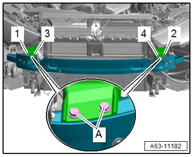
Front Impact Member - Tightening Specification and Sequence
- Tighten the bolts -A- to 23 Nm in the following sequence: -1 through 4-.
READ NEXT:
 Front Bumper Cover, Removing and Installing
To complete the procedure, a second technician is required to be at the
following position.
Special tools and workshop equipment
required
Pliers -T40172C-
Adapter -T40172/1-
Removing
- Push
Air Intake Grille, Removing and Installing
Air Intake Grille, Removing and Installing, Center
Removing
- Remove the front bumper cover end plate. Refer to
→ Chapter "Front Bumper Cover End Plate, Removing and
Installing".
- F
Impact Member, Removing and Installing
Follow the safety precautions. Refer to
→ Body Interior; Rep. Gr.00; Safety Precautions; Safety
Precautions when Working on Pyrotechnic Components.
- Remove the bumper cover.
SEE MORE:
Rear Door Trim Panels
Overview - Rear Door Trim Panel
1 - Bolt
2.5 Nm
For door trim panel
Quantity: 3
2 - Rear Entry Lamp
Driver Side Rear Entry Lamp -W83-
Passenger Side Rear Entry Lamp -W84-
Component location overview. Refer to
→ Electrical Equipment; Rep. Gr.96; Lamps
Panoramic glass roof
Operating the pa mic glass roof and
roof sunshade
Applies to: vehicles with panoramic glass roof and roof sunshade
Fig. 41 Headliner: panoramic glass roof and sunshade*
buttons
The control buttons are equipped with a twostage
function.
When tilting or opening the roof, the roof sunshade
will open
