Audi A4: Front Lid
Overview - Front Lid
Overview - Hood
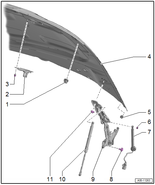
1 - Adjusting Buffer
- Adjusting. Refer to → Chapter "Height, Adjusting using Adjusting Buffer".
2 - Striker
- Removing and installing. Refer to → Chapter "Striker, Removing and Installing".
- Adjusting. Refer to → Chapter "Side and Height Adjustment at Striker".
3 - Nut
- 9 Nm
- Quantity: 3
4 - Front Lid
- Removing and installing. Refer to → Chapter "Front Lid, Removing and Installing".
- Removed pedestrian protection: Reset the hinge. Refer to → Chapter "Hinge, Resetting"
- Adjusting. Refer to → Chapter "Front Lid, Adjusting".
5 - Adjusting Buffer
- Adjusting. Refer to → Chapter "Height, Adjusting using Adjusting Buffer".
6 - Clip
7 - Pedestrian Protection Trigger
- Market-Specific Version
- Removing and installing. Refer to → Body Interior; Rep. Gr.69; Pedestrian Protection; Overview - Pedestrian Protection.
8 - Bolt
- 21 Nm
- Quantity: 2
9 - Hinge
- Removing and installing. Refer to → Chapter "Hinges, Removing and Installing".
10 - Gas-Filled Strut
- Removing and installing. Refer to → Chapter "Gas-Filled Strut, Removing and Installing".
- Venting. Refer to → Chapter "Gas-Filled Strut, Venting".
11 - Nut
- 21 Nm
- Quantity: 2
Overview - Insulation and Impact Guard on Hood
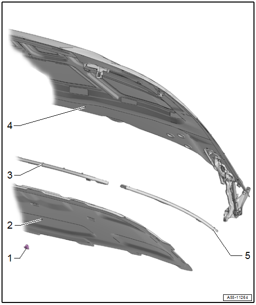
1 - Clip
- For the insulation
2 - Insulation
- Removing and installing. Refer to → Chapter "Insulation, Removing and Installing".
3 - Center Impact Guard
- Removing and installing. Refer to → Chapter "Impact Guard, Removing and Installing, Center".
4 - Front Lid
5 - Side Impact Guard
- Removing and installing. Refer to → Chapter "Impact Guard, Removing and Installing, Side".
Overview - Release Cable
Overview - Release in Vehicle Interior
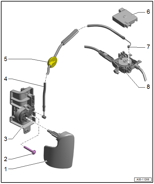
1 - Latch Release Lever
- Removing and installing. Refer to → Chapter "Latch Release Lever, Removing and Installing".
2 - Bolt
- 2 Nm
- Quantity: 2
3 - Mounting Bracket
- For latch release lever
- Removing and installing. Refer to → Chapter "Latch Release Lever Mounting Bracket, Removing and Installing".
4 - Release Cable
- For the latch
- Removing and installing. Refer to → Chapter "Latch Release Cable, Removing and Installing".
5 - Grommet
- Check for proper seating
6 - Cap
7 - Nipple
- Is inserted in the coupling guide element
8 - Coupling with Release Cables
- For the latches
- Removing and installing. Refer to → Chapter "Latch Release Cable, Removing and Installing".
Overview - Release on Latch
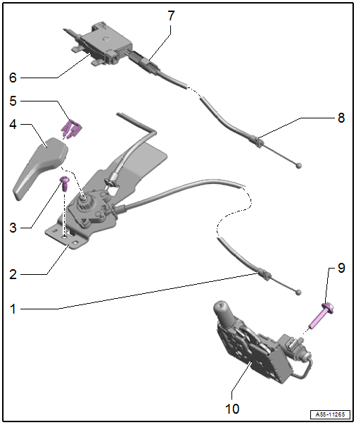
1 - Release Cable
- For releasing latches
- Removing and installing. Refer to → Chapter "Latch Release Cable, Removing and Installing".
2 - Mounting Bracket with Release Cable
- For the hook release lever
- Removing and installing. Refer to → Chapter "Mounting Bracket with Hook Release Lever Release Cable, Removing and Installing".
3 - Bolt
- 4.5 Nm
4 - Hook Release Lever
- Removing and installing. Refer to → Chapter "Hook Release Lever, Removing and Installing".
5 - Clip
- For the release lever
6 - Coupling with Release Cables
- For the latches
- Removing and installing. Refer to → Chapter "Latch Release Cable, Removing and Installing".
7 - Adjusting Thumbwheel
- For the release cable
- For adjusting the trigger point for the latches
8 - Release Cable
- For releasing latches
- Removing and installing. Refer to → Chapter "Latch Release Cable, Removing and Installing".
9 - Bolt
- Quantity: 2
- 12 Nm
10 - Latch
- Removing and installing. Refer to → Chapter "Latch, Removing and Installing".
READ NEXT:
 Front Lid, Removing and Installing
To complete the procedure, a second technician is required to be at the
following position.
NOTICE
Risk of damaging the hood by opening when the pedestrian
protection is triggered.
-
Hinge, Resetting
To complete the procedure, a second technician is required to be at the
following position.
NOTICE
Risk of damaging the hood by opening when the pedestrian
protection is triggered.
-
Release Cable, Removing and Installing
Latch Release Cable, Removing and Installing
Removing
- Remove the vehicle electrical system control module bracket.
Refer to
→ Electrical Equipment; Rep. Gr.97; Relay Panels,
SEE MORE:
Windshield
Overview - Windshield
1 -
Windshield
Removing and installing. Refer to
→ Chapter "Windshield, Removing and Installing".
Distance to roof: Dimension -c- = 2.5 mm
Distance to A-pillars: Dimension -e- =
greater than 3 mm; center if necessary
2 -
Adhesive Bead
Observe
Child safety lock
The child safety lock prevents the rear doors
from being opened from the inside and the rear
power windows from being operated.
Fig. 37 Drivers door: controls
Applies to: vehicles with manual child safety locks
Fig. 38 Rear door: manual child safety lock
Vehicles with button
Applies to: vehicles
