Audi A4: General Information
Vehicles with a High Voltage System (Hybrid Vehicles)
Extremely Dangerous Due to High-Voltage
The high-voltage system is under high-voltage. Death or serious bodily injury by electric shock.
- Individuals with electronic/medical life- and health sustaining machines in or on their person cannot perform any work on high-voltage systems. Life- and health sustaining machines are for example pain killer pumps, implanted defibrillators, pacemakers, insulin pumps, and hearing aids.
- Have the high-voltage system de-energized by a qualified person.
There is a Risk Of Injury from the Engine Starting Unexpectedly
On electric - hybrid vehicles an active ready mode is difficult to identify. Parts of the body can be clamped or pulled.
- Turn off the ignition.
- Place the ignition key outside of the vehicle interior.
Risk of Damaging the High-Voltage Cables
Misuse can damage the insulation of high-voltage cables or high-voltage connectors.
- Never support objects on the high-voltage cables and the high-voltage connectors.
- Never support tools on the high-voltage cables and the high-voltage connectors.
- Never sharply bend or kink the high-voltage cables.
- When connecting pay attention to the coding of the high-voltage connectors.
- For all procedures on vehicles with high-voltage system pay attention to the additional warning message for these vehicles. Refer to → Chapter "Warnings when Working on Vehicles with High Voltage System".
- If procedures are necessary near components of the high-voltage system "perform a visual inspection of the damage of the high-voltage components and lines". Refer to → Chapter "Performing a Visual Inspection of Damage to High Voltage Components and Cables".
- If work on the components of the high-voltage system is necessity, de-energize the high-voltage system. Refer to → Rep. Gr.93; High-Voltage System, De-Energizing or → Electrical Equipment; Rep. Gr.93; High-Voltage System, De-Energizing.
- Charge the vehicle battery, for example, using the Battery Charger -VAS5904- in the battery support mode to minimize the number of automatic starts during the test- and measuring procedures while the ready mode is active. Refer to → Electrical Equipment General Information; Rep. Gr.27; Battery; Charging the Battery and → Electrical Equipment; Rep. Gr.93; General Notes for Working on the High Voltage System.
- Move the selector level into position "P", activate the parking brake and arrange the necessary tools for testing and measuring procedures that require the ready mode to be active or that require the ignition to be on, so that they cannot come into contact with the turning components in the engine and so that they are not in the vicinity of the turning components of a running engine.
 Note
Note
- Also move the selector lever into position "P" and activate the parking brake for testing and measuring procedures which require the ignition to be on, but do not require the ready mode to be active.
- The ready mode is displayed in the Instrument Cluster Control Module -J285- above the "powermeter". Refer to Owner's Manual.
- Activate and deactivate the ready mode. Refer to Owner's Manual (consult the display in the Instrument Cluster Control Module -J285-).
All Vehicles
 Caution
- If it is suspected that chemicals were added to the refrigerant circuit to seal leaks, chemical substances to seal leaks in the refrigerant circuit (leak stop additive), do not connect the A/C service station, do not extract the refrigerant and do not clean (flush).
- Chemicals that seal leaks in the coolant circuit form deposits that affect the function of the A/C system and lead to failure of the A/C system and the A/C service station.
- Inform that customer that there are substances in the A/C system that are no approved by Volkswagen and for this reason the climate control system cannot be cleaned (flushed) or serviced.
Note
- Audi does not approve the use of chemicals to seal leaks in the refrigerant circuit (leak stop additives).
- Chemical materials (leak stop additives) to seal leaks in the refrigerant circuit react with air or the moisture in the air and form deposits in the refrigerant circuit (and in the A/C service station) that lead to malfunctions in the valves and other components that come into contact with such chemicals. These deposits cannot be removed completely from the components, even by cleaning/flushing. It is only possible to service the refrigerant circuit by replacing all the components which come in contact with this material.
- It is not possible to recognize chemical substances to seal leaks in the refrigerant circuit (leak stop additive) and the label that is supposed to come with them is usually not there. Therefore be careful when working with if you do not know its service history.
- Refrigerant circuit must be cleaned (flushed) with refrigerant R134a in order to force out moisture and other contaminants as well as old refrigerant oil as efficiently as possible, without wasting refrigerant, without the need for extensive assembly work and without endangering the environment.
Flush the refrigerant circuit:
- In the event of dirt or other contamination in the circuit.
- If vacuum reading is not maintained on evacuating a leak-free refrigerant circuit (pressure build-up due to moisture in refrigerant circuit).
- The refrigerant circuit has been left open for longer than normal (for example, following an accident).
- Pressure and temperature measurements in the refrigerant circuit indicate the likelihood of moisture.
- In the event of doubt about the amount of refrigerant oil in the circuit.
- The A/C compressor had to be replaced on account of internal damage (for example, noise or no output).
Note
- Pay attentions when replacing the Electrical A/C Compressor -V470- on vehicles with electrically driven A/C compressor (if the electronic on the A/C compressor is damaged the refrigerant circuit must not always be cleaned. Refer to → Chapter "Compressor, Replacing without the Need for Flushing Refrigerant Circuit".
- If a faulty A/C compressor is replaced with an A/C compressor from another manufacturer check for the A/C compressor to be installed has the same refrigerant oil approved which is already in the refrigerant circuit (from the removed A/C compressor). If a different refrigerant oil is approved for the A/C compressor to be installed then the A/C compressor which was removed, the refrigerant circuit must be flushed. Refer to → Chapter "Approved Refrigerant Oils".
- If it is stipulated by the vehicle-specific repair manual following the replacement of certain components.
Tools required
- A/C Service Station with Flushing Device (on these A/C service stations, the auxiliary function "flush refrigerant circuit" and the refrigerant circuit flushing device required for it are present on these A/C service stations). Refer to the Parts Catalog (Tools; Special Tools and Equipment: A/C and Heating).
- Refrigerant Circuits Adapter Set 1 -VAS6338/1-. Refer to → Chapter "Adapter for Assembling Flushing Circuit" and the Parts Catalog (Tools; Special Tools and Equipment: A/C and Heating).
Note
- If a A/C Service Station with Flushing Device is not available, it is possible to flush the refrigerant circuit with (with refrigerant R134a) the flushing device available using Refrigerant Circuit Flushing Device, however the procedure must be done manually. Refer to the Parts Catalog.
- On vehicles with screw connections on the refrigerant circuit, the A/C Adapter Set Adapter 7 -VAG1785/7- and A/C Adapter Set Adapter 8 -VAG1785/8- from Refrigerant Circuits Adapter Set 1 -VAS6338/1- can be used; on vehicles with screw connections at the A/C compressor and reservoir, two A/C Adapter Set - Adapter 8 -VAG1785/8- are required.
- In Refrigerant Circuits Adapter Set 1 -VAS6338/1-, there is also a Refrigerant Circuits Adapter Set 1 - Adapter 31 -VAS6338/31- with connections 5/8 -18 UNF and large inner diameter in short version (commercially available).
Preliminary Work
- Discharge refrigerant circuit. Refer to → Chapter "Refrigerant Circuit, Discharging with Service Station".
- Remove the A/C compressor. Refer to → Heating, Ventilation and Air Conditioning; Rep. Gr.87; A/C Compressor (vehicle-specific repair manual).
On a vehicle with restrictor and reservoir
- Remove restrictor (vehicle-specific) and reconnect lines → Heating, Ventilation and Air Conditioning; Rep. Gr.87; System Overview - Refrigerant Circuit (vehicle-specific repair manual).
- Remove reservoir (vehicle-specific) and reconnect the lines (use adapters and Refrigerant Circuits Adapter Set 1 - Adapter 31 -VAS6338/31- from the Refrigerant Circuits Adapter Set 1 -VAS6338/1-). Refer to → Chapter "Adapter for Assembling Flushing Circuit" and → Heating, Ventilation and Air Conditioning; Rep. Gr.87; System Overview - Refrigerant Circuit (vehicle-specific repair manual).
Note
- Depending on the version, the reservoir could be potentially flushed but it will take too much refrigerant because of its large internal volume; the reservoir would ice-up too much when extracting the refrigerant, the refrigerant would evaporate too slowly and the extraction process would take too long.
- Depending on the version, the receiver/dryer can be potentially flushed (see vehicle-specific description) but it will take too much refrigerant because of its large internal volume; the receiver/dryer would ice-up too much when extracting the refrigerant, the refrigerant would evaporate too slowly and the extraction process would take too long.
On a vehicle with expansion valve and receiver/dryer
- Remove receiver/dryer (vehicle-specific, not necessity on all vehicles) and reconnect the lines (use adapters and Refrigerant Circuits Adapter Set 1 - Adapter 31 -VAS6338/31- from the Refrigerant Circuits Adapter Set 1 -VAS6338/1-). Refer to → Chapter "Adapter for Assembling Flushing Circuit" and → Heating, Ventilation and Air Conditioning; Rep. Gr.87; System Overview - Refrigerant Circuit (vehicle-specific repair manual).
Note
- The receiver/dryer can be flushed depending on the version (remove dryer cartridge if necessary). Refer to → Chapter "Adapter for Assembling Flushing Circuit" and → Heating, Ventilation and Air Conditioning; Rep. Gr.87; System Overview - Refrigerant Circuit (vehicle-specific repair manual).
- The receiver/dryer connected to the condenser (for example on model Audi A3 from model year 2004) remains installed during flushing (it can be flushed due to its design and is only replaced after flushing). Refer to → Chapter "Adapter for Assembling Flushing Circuit" and → Heating, Ventilation and Air Conditioning; Rep. Gr.87; System Overview - Refrigerant Circuit (vehicle-specific repair manual).
- If the receiver/dryer or dryer cartridge is integrated in the condenser, then they cannot be replaced separately or are not available as a single part, and the condenser must be replaced. Replace the condenser with the receiver/dryer on these vehicles. Refer to → Heating, Ventilation and Air Conditioning; Rep. Gr.87; System Overview - Refrigerant Circuit and Parts Catalog.
- Receivers/dryers where it is possible to replace the dryer cartridge have an additional filter, which must also be replaced with the dryer cartridge.
- Remove dryer cartridge from vehicles with dryer partridge in receiver/dryer that is connected to the condenser (vehicle-specific), and seal opening on receiver/dryer. Refer to → Heating, Ventilation and Air Conditioning; Rep. Gr.87; System Overview - Refrigerant Circuit (vehicle-specific repair manual).
- Remove expansion valve (vehicle-specific) and install one adapter from the Refrigerant Circuits Adapter Set 1 -VAS6338/1-. Refer to → Chapter "Adapter for Assembling Flushing Circuit" and → Heating, Ventilation and Air Conditioning; Rep. Gr.87; System Overview - Refrigerant Circuit (vehicle-specific repair manual).
- For vehicles with multiple shut-off valves and check valves, remove the valve and install the corresponding adapter (or hand shut-off valves) from the Refrigerant Circuits Adapter Set 1 -VAS6338/1-. Refer to → Chapter "Adapter for Assembling Flushing Circuit" and → Heating, Ventilation and Air Conditioning; Rep. Gr.87; Refrigerant Circuit; System Overview - Refrigerant Circuit (vehicle-specific repair manual).
Note
If there is no adapter suitable for the expansion valve in the Refrigerant Circuits Adapter Set 1 -VAS6338/1-, the removed expansion valve can also be drilled open (the old expansion valve must also be replaced in most cases and is therefore no longer required).
Caution
- Make sure the sealing surfaces on the expansion valve are not damaged when drilling open.
- Refrigerant will otherwise escape if the sealing surface is damaged.
Drill a hole for the expansion valve.
Note
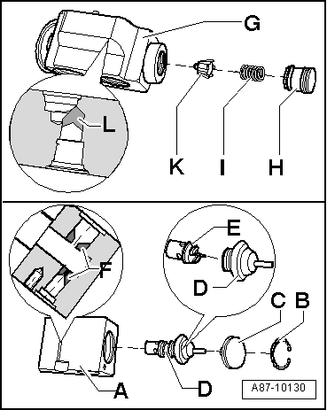
- Before drilling open, remove the regulating element and drill open the expansion valve using a suitable drill, for example (drill bit diameter 6.0 mm, for example).
- Several components are to be removed from expansion valve before drilling open.
- Expansion valves are available in various versions and with different constructions. For version -A-, for example. parts -B-, -C- and -D- must be removed. Separate part -E- (regulating element) from component -D-. Then drill open expansion valve in area -F- using a suitable drill.
- For version -G- for example, parts -H-, -I- and -K- must be removed and then drill the open area -L- using a suitable drill.
- Clean the drilled open expansion valve of residue from the work (shavings).
- Install the parts -B-, -C- and -D- for version -A-, or the part -H- for version -G-.
Note
On vehicles with two evaporators, disconnect second evaporator circuit from first evaporator circuit and flush separately. Refer to → Chapter "Adapter for Assembling Flushing Circuit" and → Heating, Ventilation and Air Conditioning; Rep. Gr.87; System Overview - Refrigerant Circuit (vehicle-specific repair manual).
Flushing
- Check refrigerant quantity in the A/C service station, there must be at least 6 kg of refrigerant R134a.
Note
If necessary, turn on the heating installed in the service station for the refrigerant container before the first flushing (to increase the pressure in the refrigerant container) and turn it off before first extraction during flushing.
- Drain the old oil container of the A/C service station.
- Connect the supply hose (high pressure side) of A/C service station to the low pressure line leading to the A/C compressor (line with larger diameter) using an adapter. Refer to → Chapter "Adapter for Assembling Flushing Circuit".
- Connect the return hose (low pressure- or intake side) of the A/C service station to the output of the refrigerant circuit flushing device.
- Connect the input on the refrigerant circuit flushing device to the high pressure line leading to the A/C compressor (line with smaller diameter) using an adapter. Refer to → Chapter "Adapter for Assembling Flushing Circuit".
Note
- Components are always (with the exception of the electrical A/C compressor) flushed in the opposite direction of refrigerant flow when the A/C system is in operation. Refer to → Chapter "Flushing Circuit Block Diagrams".
- While flushing, contaminants from the refrigerant circuit enter the refrigerant circuit flushing device and the A/C service station and are absorbed by the filters and dryers installed there. Depending on the contaminant, these components are to be replaced in shorter intervals in line with operating instructions for A/C service station or refrigerant circuit flushing device.
- The filter in the refrigerant circuit flushing device depends on the type and degree of contamination in the flushed refrigerant circuit, it should be changed after five to ten flushing cycles (flushed vehicles) at the latest. If a heavily contaminated refrigerant circuit is flushed (the refrigerant oil from the circuit is black and viscous or there are many shavings in the refrigerant circuit), the filter should be replaced after flushing. With a refrigerant circuit heavily contaminated in this way, it is wise to flush the circuit again after changing the filter.
- Depending on the type of contamination, dirt (old refrigerant oil and abraded material from A/C compressor) is deposited on the viewing glass. Clean the viewing glass after flushing if necessary, and flush the refrigerant circuit once more with one flushing procedure as a check (one cycle is sufficient).
- Liquid refrigerant cannot be led through the expansion valve, restrictor and dryer bag of certain receiver/dryers at an appropriate speed, therefore these components must be removed and replaced by adapters if necessary → Heating, Ventilation and Air Conditioning; Rep. Gr.87; System Overview - Refrigerant Circuit (vehicle-specific repair manual).
- For adapters for connecting the A/C service station and for bridging certain components of refrigerant circuit. Refer to → Chapter "Adapter for Assembling Flushing Circuit".
- Remove the flushing circuit depending on the refrigerant circuit in the vehicle. Refer to → Chapter "Adapter for Assembling Flushing Circuit".
Vehicles with two evaporators in the refrigerant circuit:
Note
- The refrigerant circuit is cleaned in two flushing cycles (first the section with the evaporator in the front heater and A/C unit and then the section with the evaporator in the rear heater and A/C unit. Refer to → Chapter "Adapter for Assembling Flushing Circuit".
- On vehicles with two evaporators, disconnect second evaporator circuit from first evaporator circuit and flush separately. Refer to → Chapter "Adapter for Assembling Flushing Circuit" and → Heating, Ventilation and Air Conditioning; Rep. Gr.87; System Overview - Refrigerant Circuit (vehicle-specific repair manual).
Vehicles with high-voltage system (without additional functions of the A/C system for example on the Audi A3 e-tron, Q5 hybrid etc.):
Note
- The refrigerant circuit is cleaned in two flushing cycles (first the section with the evaporator in the front heater and A/C unit and then the section with the high-voltage battery heat exchanger or the evaporator in the battery cooling module). Refer to → Chapter "Adapter for Assembling Flushing Circuit".
- On vehicles with two evaporators or an evaporator with a heat exchanger, disconnect second evaporator circuit from first evaporator circuit or to the evaporator via a hand shut-off valve and flush separately. Refer to → Chapter "Adapter for Assembling Flushing Circuit" and → Heating, Ventilation and Air Conditioning; Rep. Gr.87; System Overview - Refrigerant Circuit (vehicle-specific repair manual).
- A flushing circuit is comprised of three flushing procedures one after the other (depending on the program in the respective A/C service station).
- If necessary close or open the installed hand shut-off valves depending on which section of the refrigerant circuit should be flushed in this flushing circuit.
- Close or open the equipped electrically powered valves using the designated routine in the corresponding vehicle control module depending on which section of the refrigerant circuit is to be flushed in this flush cycle.
Vehicles with a high-voltage system (with additional functions of the A/C system such as heat pump operation for example on the Audi Q7 e-tron etc.):
Note
- The refrigerant circuit is cleaned in multiple flushing cycles. Refer to → Chapter "Adapter for Assembling Flushing Circuit" and → Heating, Ventilation and Air Conditioning; Rep. Gr.87; Refrigerant Circuit (Cleaning the A/C system refrigerant circuit).
- To flush the refrigerant circuit is divided into multiple sections and then cleaned respectively in a flushing cycle. The division takes place by activating the installed electrically activated valves and via the installed manually activated hand shut-off valves. Refer to → Heating, Ventilation and Air Conditioning; Rep. Gr.87; Refrigerant Circuit (Cleaning the A/C system refrigerant circuit).
- A flushing circuit is comprised of three flushing procedures one after the other (depending on the program in the respective A/C service station).
- The design of the different flushing circuits for these vehicles is described in the respective vehicle-specific repair manual. Refer to → Heating, Ventilation and Air Conditioning; Rep. Gr.87; Refrigerant Circuit (Cleaning the A/C system refrigerant circuit).
- Closing or opening the installed hand shut-off valves depends on which section of the refrigerant circuit should be flushed in this flushing circuit. Refer to → Heating, Ventilation and Air Conditioning; Rep. Gr.87; Refrigerant Circuit (Cleaning the A/C system refrigerant circuit).
- Close or open the equipped electrically powered valves using the designated routine in the corresponding vehicle control module depending on which section of the refrigerant circuit is to be flushed in this flush cycle. Use the Vehicle Diagnostic Tester in the "Guided Fault Finding" flushing and the → Heating, Ventilation and Air Conditioning; Rep. Gr.87; Refrigerant Circuit (Cleaning the A/C system refrigerant circuit).
All Vehicles
- Turn on the A/C service station and flush the refrigerant circuit (duration approximately one to one and a half hours for one flushing cycle with three flushing operations).
Note
- Perform flushing procedure according to operating instructions of the A/C service station. Refer to the operating instructions for the A/C service station.
- Depending on version of A/C service station, old oil container holds only approximately 125 cm 3 refrigerant oil, in the event a system with a larger quantity of refrigerant oil must be flushed, it may be necessary to drain the old oil container after the first flushing process of one flushing cycle.
- Observe the refrigerant which flows back into the A/C service station from the refrigerant circuit, only when the refrigerant streams clear and completely colorless through the viewing glass of refrigerant circuit flushing device into the A/C service station is the refrigerant circuit cleaned.
- While flushing, all the refrigerant oil is washed out of the refrigerant circuit (up to a very small amount, for example in the evaporator, however this can be disregarded).
- If heavily contaminated, it may be necessary to perform the flushing procedure twice (two flushing cycles with three flushing operations each).
Sequence of flushing procedure (sequence occurs automatically according to the A/C service station program)
- After turning on, the flushing circuit (refrigerant circuit with connecting hoses and flushing equipment for refrigerant circuits) is evacuated first and the refrigerant circuit is checked for leaks during this. Depending on the A/C service station version, it is possible that manually switching to advance the program is required. Refer to the operating instructions for the A/C service station.
- A prescribed quantity of refrigerant (such as 5 kg) is filled into the evacuated refrigerant circuit via the high pressure side of the A/C service station (in opposite direction of normal flow when A/C system is in operation and also on the low pressure side of the vehicle refrigerant circuit), or, as much refrigerant is filled until refrigerant circuit and viewing glasses of refrigerant circuit flushing device are completely filled with fluid refrigerant (depending on version of A/C service station, recognized, for example, that refrigerant no longer flows from behind over a certain time period).
- After the prescribed quantity of refrigerant has been filled, for example, the heater for the refrigerant circuit flushing device is turned on (only in the event the refrigerant is extracted in gaseous form from the refrigerant circuit flushing device), depending on version of A/C service station and refrigerant circuit flushing device.
- After the refrigerant was extracted, the heating of the flushing device for refrigerant circuits is switched off (if present), it may occur that the refrigerant circuit is shortly evacuated again, depending on its version. After evacuation, the refrigerant extracted from the refrigerant circuit is deposited by the service station.
- The sequence of filling refrigerant, extracting (and evacuating) is repeated twice (performed a total of three times). Refer to the operating instructions for the A/C service station.
- After the third extraction, the flushing circuit is evacuated depending on the version of the A/C service station.
- After the flushing procedure has ended, check the viewing glass(es) of refrigerant circuit flushing device, if they are soiled, clean them if necessary according to operating instructions of the refrigerant circuit flushing device or of the A/C service station and perform the flushing procedure once more as a test (one cycle is sufficient, duration approximately 30 minutes). refer to the operating instructions for the A/C service station.
- Check the pressure in the refrigerant circuit, there must be no positive pressure in the refrigerant circuit (evacuate briefly once more if necessary).
- Disconnect the connections to the A/C service station from the vehicle refrigerant circuit (there must be no positive pressure in the refrigerant circuit).
- Replace these components depending on equipment (restrictor and reservoir, expansion valve and receiver/dryer or dryer cartridge in the receiver/dryer). Refer to → Heating, Ventilation and Air Conditioning; Rep. Gr.87; System Overview - Refrigerant Circuit (vehicle-specific repair manual) and the Parts Catalog.
- Replace the A/C compressor, depending on its condition. Refer to → Heating, Ventilation and Air Conditioning; Rep. Gr.87; A/C Compressor (vehicle-specific repair manual) and Parts Catalog or drain the rest of the refrigerant oil still inside the removed A/C compressor. Refer to → Chapter "Refrigerant Circuit Components, Replacing" (replace the refrigerant circuit components) and will new refrigerant. Refer to → Chapter "Approved Refrigerant Oils and Capacities" (Approved Refrigerant Oils and Capacities).
Note
- There is a defined and prescribed amount of refrigerant oil in the replacement compressor. If the vehicle has two evaporators, then there refrigerant circuit requires a specific quantity of refrigerant oil. Refer to → Heating, Ventilation and Air Conditioning; Rep. Gr.87; System Overview - Refrigerant Circuit (vehicle-specific repair manual) and → Chapter "Approved Refrigerant Oils and Capacities". (Approved Refrigerant Oils and Capacities).
- If the A/C compressor is not be replaced, the quantity of refrigerant oil in the A/C compressor must be topped off to the prescribed capacity (tilt the refrigerant oil out and refill the prescribed quantity into the A/C compressor or refrigerant circuit). Refer to → Chapter "Refrigerant Circuit Components, Replacing" (replacing refrigerant circuit components) and → Chapter "Approved Refrigerant Oils and Capacities". Approved Refrigerant Oils and Capacities).
- Reassemble the refrigerant circuit completely. Refer to → Heating, Ventilation and Air Conditioning; Rep. Gr.87; System Overview - Refrigerant Circuit (vehicle-specific repair manual).
- Evacuate and recharge the refrigerant circuit according to specification. Refer to → Chapter "Refrigerant Circuit, Discharging with Service Station" and → Chapter "Refrigerant Circuit, Charging with Service Station".
- Start up A/C system according to specification. Refer to → Heating, Ventilation and Air Conditioning; Rep. Gr.87; Refrigerant Circuit; A/C System, Starting Operation after Filling Refrigerant Circuit (vehicle-specific repair manual) and → Chapter "A/C System, Operating after Charging".
READ NEXT:
 Flushing Circuit Block Diagrams
Note
The arrows in the following illustrations show the direction
of refrigerant flow during flushing (refrigerant flows in
opposite direction of flow when Air Conditioning (A/C) system is
Electrically Driven A/C Compressor, Rinsing (Remove Refrigerant Oil)
Vehicles with a High Voltage System (Hybrid Vehicles)
Extremely Dangerous Due to High-Voltage
The high-voltage system is under high-voltage. Death or serious
bodily injury by electric shock.
- I
Adapter for Assembling Flushing Circuit
Various adapters which are required to connect the Air
Conditioning (A/C) service station to the refrigerant circuit
for flushing and to bridge the removed receiver/dryer or
reservoir and expansi
SEE MORE:
Door Handle, Removing and Installing
Removing
- Remove the door handle trim. Refer to
→ Chapter "Door Handle Trim, Removing and Installing".
- If equipped, remove the exterior door handle illumination bulb.
Refer to
→ Electrical Equipment; Rep. Gr.94; Exterior Door Handle Lamps;
Exterior Door Handl
Rearview Camera -R189-, Removing and Installing
Rearview Camera -R189-, Removing and Installing, Sedan
The Rearview Camera -R189- is inside the rear lid handle
button. It permanently attached to the handle button.
If the Rearview Camera -R189- must be replaced, then the
handle button must also be replaced.
Removing
- Turn off the ignition
