Audi A4: Interior Rearview Mirror
Overview - Interior Rearview Mirror
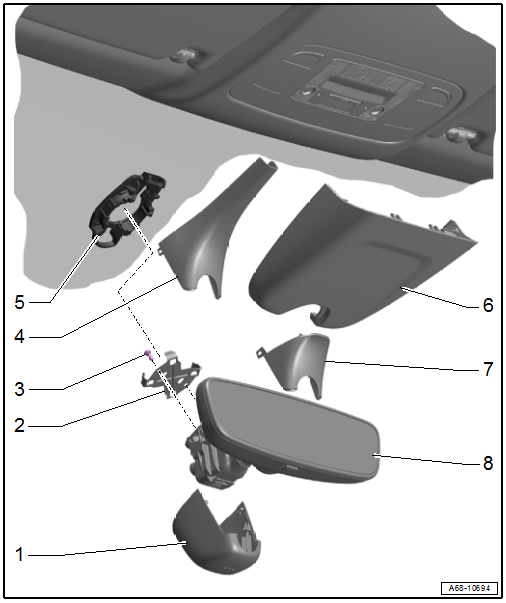
1 - Front Cover
- For the mirror base
- Press on until it engages audibly
2 - Clip
- For the interior rearview mirror
- Replace after removing the interior rearview mirror
3 - Bolt
- 1.5 Nm
- Quantity: 2
4 - Rear Cover
- For the mirror base
- For the interior rearview mirror without optional equipment
- Press on until it engages audibly
5 - Retaining Plate
- For the interior rearview mirror
- Attached to the windshield
6 - Cover
- For the control module sensor
- For the interior rearview mirror with optional equipment
- Press on until it engages audibly
7 - Rear Cover
- For the mirror base
- For the interior rearview mirror with optional equipment
- Press on until it engages audibly
8 - Interior Rearview Mirror
- Equipment level: With integrated Automatic High Beam Assist Control Module -J844-
- The Automatic High Beam Assist Control Module -J844- cannot be replaced separately. Replace the interior rearview mirror if faulty
- Removing and installing. Refer to → Chapter "Interior Rearview Mirror, Removing and Installing".
- Mount to the installation position tilted 20º and turn it clockwise until it stops
- Replace the clip after removing
Interior Rearview Mirror, Removing and Installing
Special tools and workshop equipment required
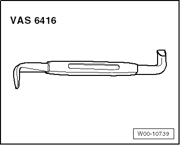
- Angled Screwdriver -VAS6416-
 Caution
This procedure contains mandatory replaceable parts. Refer to component overview and parts catalog prior to starting procedure.
Mandatory Replacement Parts
- Clip - Interior Rearview Mirror to Retaining Plate
Removing
 WARNING
Health risk due to electrolyte.
Follow the safety precautions for the automatic dimming interior rearview mirror. Refer to → Chapter "Safety Precautions, Automatic Dimming Interior Rearview Mirror".
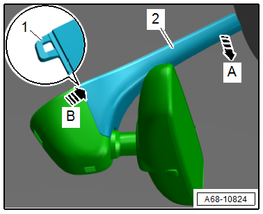
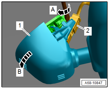
- Tilt the interior rearview mirror downward until it stops, approximately 25º.
- Pull the rear cover -2- downward in the direction of -arrow A- and at the same time release the catches -1- by pressing firmly on the cover in the direction of -arrow B-.
- Disengage the cover from the mirror base and remove.
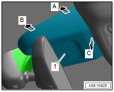
Interior Rearview Mirror with Optional Equipment
- To unclip the cover in the direction of -arrows A, B and C- insert the Angled Screwdriver -VAS6416- carefully between the windshield and the cover.
- Repeat the procedure on the opposite side.
- Disengage the front of the cover -1- and remove it toward the rear.
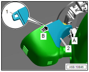
- Pull the rear cover -2- downward in the direction of -arrow A- and at the same time release the catches -1- by pressing firmly on the cover in the direction of -arrow B-.
- Disengage the cover from the mirror base and remove.
Continuation for All Mirror Versions
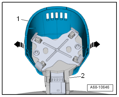
- Place a screwdriver between the retaining plate and the mirror base.
- Carefully turn the screwdriver on its axis in the direction of -arrow A-, until the retaining tab disengages from the baseplate.
- At the same time turn the mirror base -1- counterclockwise in the direction of -arrow B- until it stops.
- Remove the interior rearview mirror from the baseplate and disconnect the connector -2-.
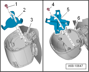
- Carefully disengage the tabs in the direction of -arrows- and remove the front cover -1- downward out of the guide rods on the interior rearview mirror base -2-.
Installing
Install in reverse order of removal and note the following:
- Replace the clip -2 or 5- after removing the interior rearview mirror. Refer to the Parts Catalog for the allocation.
- Position the interior rearview mirror tilted 20º with respect to the installation position.
- Turn the interior rearview mirror clockwise until it stops.
 Note
Note
If the interior rearview mirror with integrated Automatic High Beam Assist Control Module -J844- is replaced select the "Replace control module" function for the respective control module using the Vehicle Diagnostic Tester Diagnostic.
Installation instructions: For example tightening specifications, replacing components. Refer to → Chapter "Overview - Interior Rearview Mirror".
Automatic Dimming Function, Switching On and Off
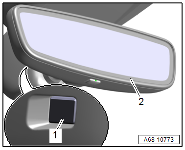
- By briefly pressing the button -2- (less than three seconds), the automatic dimming function is switched on or off automatically.
Automatic dimming "ON": The lamp in the display -1- turns on.
Automatic dimming "OFF": The lamp in the display -1- turns off.
- Automatic dimming function is activated each time the "ignition is switched on".
- If the automatic dimming function is deactivated, the function is also deactivated on the exterior rearview mirror.
- In dimming mode, the mirror surface lights up when interior lights are switched on or reverse gear is engaged.
- The interior rearview mirror automatic dimming function can only work properly if the rear window shade is raised.
Compass Display, Switching On and Off
- Press and hold the button -2- for three to six seconds. The compass display -1- changes from "ON" to "OFF" and vice versa.
Compass display "ON" - the direction is displayed.
Compass display "OFF" - the direction is not displayed.

Compass Zone, Adjusting
It is necessary to set the compass zone if:
- A new Automatic Dimming Interior Rearview Mirror -Y7- is installed.
- If the vehicle is driven a long distance over more than two zones from the originally set zone, then the new compass zone must be set again.
Compass Zone, Adjusting
- Press the button -2- for six to nine seconds until a "Z" and a compass zone number appears.
- Keep pressing the button until the number of the desired compass zone appears.
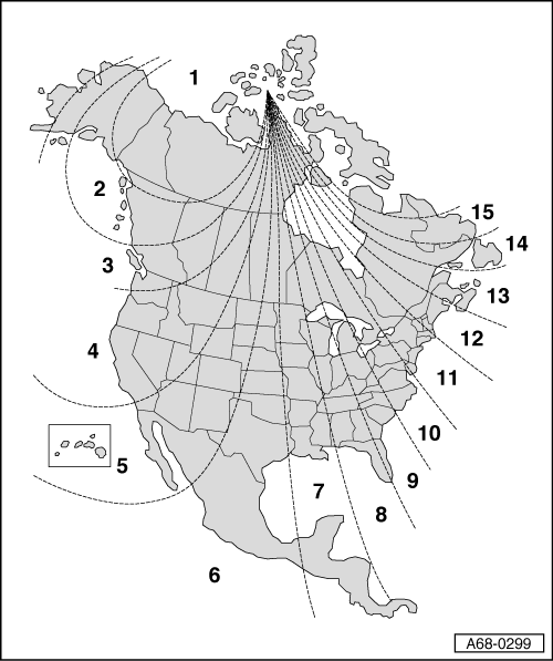
- Read the desired compass zone on the world map:
- North America.
After a few seconds, the compass display switches from the zone number of the desired compass zone to the direction.
- The interior rearview mirror automatic dimming function is reactivated after the compass zone is set. Refer to → Chapter "Compass Display, Switching On and Off".
Digital Compass, Calibrating
It is necessary to calibrate the digital compass if:
- The compass directions are not correct.
- The letter "C" instead of a direction will appear or the compass display will be blank.
- A new Automatic Dimming Interior Rearview Mirror -Y7- is installed.
The digital compass may also need to be calibrated if:
- The vehicle battery was reconnected after being disconnected for an extended period.
- A new audio system or audio system component was installed.
Digital Compass, Calibrating
- Switch the ignition on.
- The letter "C" must appear in the compass display -1-.
- If the letter "C" does not appear, press the button -2- for 9 to 12 seconds until the "C" appears in the compass display.
- Drive in a circle two to three times at about 10 km/h (5 mph) until a direction is shown in the compass display.
- The interior rearview mirror automatic dimming function is reactivated after the calibration is complete. Refer to → Chapter "Automatic Dimming Function, Switching On and Off".
Compass Zones, Reading in Different World Maps
North America
Automatic Dimming Interior Rearview Mirror, Checking Function
To check the function, the following conditions must be fulfilled:
- Interior rearview mirror installed.
- Ignition switched on.
- Reverse gear not engaged.
- Automatic-dimming function must be switched on, indicator light must come on.
Test Sequence
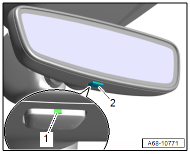
- Cover the photosensor -1- on the housing side.
- Shine a light source, such as a flashlight, in the mirror on the mirror side of the photosensor -2-.
- The interior rearview mirror must dim within a short period of time.
Special Tools
Special tools and workshop equipment required
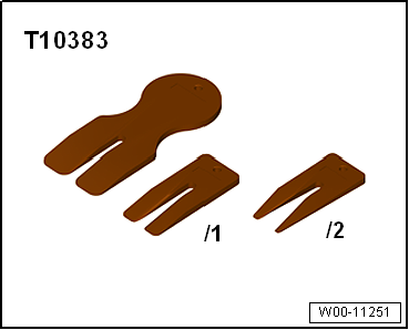
- Wedge Set -T10383-
- Wedge Set - Wedge 1 -T10383/1-
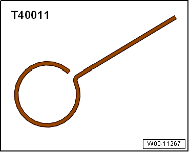
- Locking Pin (3 pc.) -T40011-
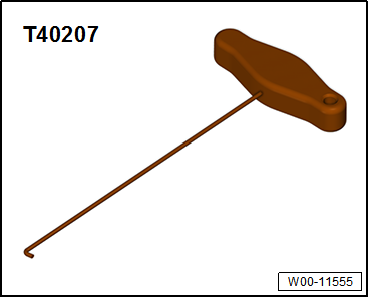
- Hook Tool -T40207-
- Angled Screwdriver -VAS6416-
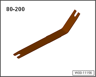
- Pry Lever -80-200-
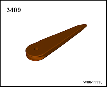
- Trim Removal Wedge -3409-
READ NEXT:
 Seat Belts
Component Location Overview - Seat Belts and Mounting Points
Note
The Avant is shown.
1 - Front Belt End Fitting
Overview. Refer to
→ Chapter "Overview - Front Three-Point
Front Three-Point Seat Belt, Removing and Installing
Caution
This procedure contains mandatory replaceable parts.
Refer to component overview and parts catalog prior to
starting procedure.
Mandatory Replacement Parts
Bolt - Automatic Belt R
SEE MORE:
Cooling system
Coolant
The engine cooling system is filled with a mixture
of purified water and coolant additive at the factory.
This coolant must not be not changed.
The coolant level is monitored using the
indicator
light. However, you should occasionally
check the coolant level.
Messages
The following messag
Automatic luggage compartment lid
Applies to: vehicles with automatic luggage compartment lid
Fig. 32 Luggage compartment lid: 1 closing button*, 2
lock button* (vehicles with convenience key*)
The luggage compartment lid can be opened and
closed automatically > in General information.
Opening the luggage compartment lid
When
