Audi A4: Locking Mechanism Trim, Removing and Installing
Special tools and workshop equipment required
- Trim Removal Wedge -3409-
Removing
- Unlock the rear seat backrest.
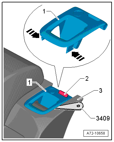
- Make sure the button -2- (indicator) is in the "up" position.
- Push the tabs in the direction of -arrows- on both sides of the trim using a -3409-.
- Remove the trim -1- upward and off the rear seat backrest -3-.
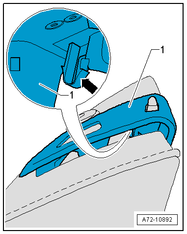
- Remove the trim -1- as far as possible upward from the rear seat backrest.
- Pry the catch -arrow- out of the locking mechanism using a flat blade screwdriver.
- Remove the trim upward from the rear seat backrest.
Installing
Install in reverse order of removal and note the following:
- Make sure the button moves easily after installing the trim.
Installation instructions: For example tightening specifications, replacing components. Refer to → Chapter "Overview - Rear Seat Backrest, Folding Backrest".
Rear Seat Backrest Locking Mechanism, Removing and Installing
Removing
- Remove the rear seat backrest. Refer to → Chapter "Rear Seat Backrest, Removing and Installing, Outer Folding Backrest".
- Remove the headrest. Refer to → Chapter "Headrest, Removing and Installing".
- Remove the rear seat backrest in the area of the locking mechanism. Refer to → Chapter "Cover and Cushion, Removing and Installing, Folding Backrest".
Vehicles with Backrest Release
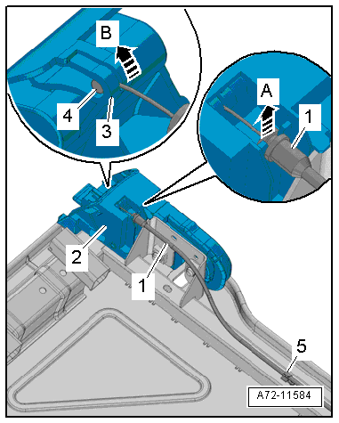
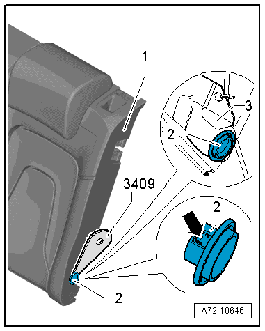
- Unclip the release cable -1- from the bracket -5- on the rear seat backrest.
- Disengage the release cable from the locking mechanism -2- in the direction of -arrow A-.
- Remove the release cable nipple -4- from the release handle -3- in the direction of -arrow B- and remove the release cable.
Continuation for All Seat Versions
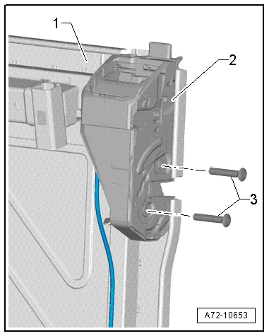
- Remove the bolts -3-.
- Remove the locking mechanism -2- from the backrest frame -1-.
Installing
Install in reverse order of removal.
Installation instructions: For example tightening specifications, replacing components. Refer to → Chapter "Overview - Rear Seat Backrest, Folding Backrest".
Lock Cylinder, Removing and Installing
Removing
- Remove the trim and the locking mechanism. Refer to → Chapter "Locking Mechanism Trim, Removing and Installing".
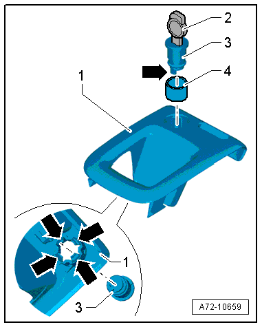
- Make sure the indicator is in the "top" position.
 Caution
Risk of destroying the lock cylinder.
The lock cylinder may only be removed and installed with the key properly inserted to prevent the tumblers and pressure springs from falling out.
- Release the four catches -lower arrows- and press the locking cylinder -3- with the key -2- out from the trim -1-.
 Note
Note
Disregard the -top arrow-.
Installing
Install in reverse order of removal and note the following:
- Pay attention to the installed position.
- Push the key -2- into the new lock cylinder correctly.
- Remove the protective cap -4- from the new lock cylinder -3-.
- Insert the lock cylinder -3- into the trim -1-. While doing so, pay attention to the installation position of the pin -top arrow-.
- Trim for the left folding backrest: The pin on the locking cylinder faces toward the rear in the direction of travel.
- Trim for the right folding backrest: The pin on the locking cylinder faces toward the front in the direction of travel.
- Also, the lock cylinder must fit correctly into the retainers -lower arrows-
Note
The trim with the left lock cylinder is shown.
- Install the trim and locking cylinder in the rear seat backrest. Refer to → Chapter "Locking Mechanism Trim, Removing and Installing".
- Turn the key counterclockwise 90º.
- Lock the backrest.
Installation instructions: For example tightening specifications, replacing components. Refer to → Chapter "Overview - Locking Mechanism".
Outer Bearing Sleeve, Removing and Installing
Special tools and workshop equipment required
- Trim Removal Wedge -3409-
Removing
- Remove the backrest. Refer to → Chapter "Rear Seat Backrest, Removing and Installing, Outer Folding Backrest".
- Unclip the bearing sleeve -2- from the backrest -1-. Do not damage the cover while doing so.
Installing
Install in reverse order of removal and note the following:
- All tabs -arrow- must engage completely in the backrest mount -3-.
Installation instructions: For example tightening specifications, replacing components. Refer to → Chapter "Overview - Rear Seat Backrest, Folding Backrest".
Inner Mounting Pin, Removing and Installing
Removing
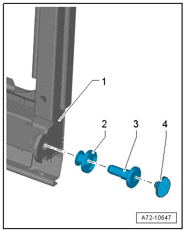
- Remove the chafe protection -4- and then remove the mounting pin -3- from the backrest frame -1-.
- Remove the bearing sleeve -2- from the mounting pin.
Note
Shown without the cushion and cover for clarity.
Installing
Install in reverse order of removal.
Installation instructions: For example tightening specifications, replacing components. Refer to → Chapter "Overview - Rear Seat Backrest, Folding Backrest".
READ NEXT:
 Center Folding Backrest Trim Panel, Removing and Installing
Special tools and workshop equipment required
Pry Lever -80-200-
Removing
- Remove the center armrest. Refer to
→ Chapter "Center Armrest, Removing and Installing".
- Remove the c
Front Seat Covers and Cushions
Overview - Seat Pan Cover and Cushion
Overview - Seat Pan Cover and Cushion, Seat without Seat Depth Adjuster
1 - Seat Pan
2 - Cushion
Covers and cushions, removing and installi
SEE MORE:
Vehicle Interior Trim Panels
Component Location Overview - Vehicle Interior Trim Panels
Component Location Overview - Vehicle Interior Trim Panels, A3 Sedan
1 - D-Pillar Trim Panel
Overview. Refer to
→ Chapter "Overview - D-Pillar Trim Panel".
2 - C-Pillar Trim Panel
Overview. Refer to
→&nbs
Shock Absorber Fork, Removing and Installing
Special tools and workshop equipment required
Spreader Tool -3424-
Torque Wrench 1331 5-50Nm -VAG1331-
Torque Wrench 1332 40-200Nm -VAG1332-
Caution
This procedure contains mandatory replaceable parts.
Refer to component overview and parts catalog prior to
starting procedure.
Mandato
