Audi A4: Overview - Flywheel and Dual Clutch
Audi A4 (B9) 2016-2026 Service Manual / Transmission / Servicing - 7-Speed Dual Clutch Transmission 0CJ, 0CL, 0CK / Clutch / Overview - Flywheel and Dual Clutch
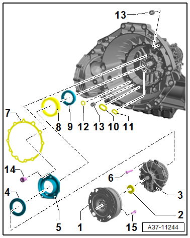
1 - Flywheel
- Refer to the Parts Catalog because there are different versions depending on the date of manufacture.
- Removing an installing. Refer to → Chapter "Flywheel, Removing and Installing".
2 - Shaft Seal
- For the input shaft
- Replacing. Refer to → Chapter "Input Shaft Seal, Replacing".
3 - Dual Clutch
- Refer to the Parts Catalog because there are different versions depending on the date of manufacture.
- Removing an installing. Refer to → Chapter "Dual Clutch, Removing and Installing".
4 - Engaging Bearing
- Pay attention to the installed position.
- Can only be replaced together with the clutch
- Removing an installing. Refer to → Chapter "Dual Clutch, Removing and Installing".
5 - Clutch Slave Cylinder
- Can only be replaced together with the clutch
- Removing an installing. Refer to → Chapter "Dual Clutch, Removing and Installing".
6 - Bolt
- 10 Nm + 90º
- Replacing
- Tighten diagonally to the tightening specification
- M8
7 - Seal
- Replacing
8 - Double Shaft Seal
- Replacing
- Removing and installing. Refer to → Chapter "Input Shaft Double Shaft Seal, Replacing".
9 - Guide Sleeve
- Pay attention to the installed position.
- Removing and installing. Refer to → Chapter "Input Shaft Double Shaft Seal, Replacing".
10 - Seal
- Replacing
11 - Seal
- Replacing
12 - Seal
- Replacing
13 - Alignment Sleeve
14 - Bolt
- 5 Nm + 30º
- Not present depending on the version.
- Tighten evenly
- M6
15 - Bolt
- 60 Nm
- M10 x 15.5
READ NEXT:
 Flywheel, Removing and Installing
Special tools and workshop equipment required
Puller - Clutch Module -T40176-
Clutch Disc Shaft Spline Lubricant -G 000 100-
Sealing Grease. Refer to the Parts Catalog.
Removing
Note
T
Dual Clutch, Removing and Installing
Special tools and workshop equipment required
Shop Crane -VAS6100-
Puller - Input Shaft -T40050-
Pressure Stand -T40099-
Guide Pins - Gearbox -T40288-
Engine Support Bridge - Additional Hooks (2
Input Shaft Double Shaft Seal, Replacing
Special tools and workshop equipment required
Puller - Crankshaft/Power Steering Seal -T20143-
Thrust Piece -T40300-
Clutch, engaging bearing and slave cylinder removed. Refer
to
→ Chap
SEE MORE:
Differential
Overview - Differential
1 - Left Flange Shaft Seal
Replacing. Refer to
→ Chapter "Left Seal, Replacing".
2 - Shim
Behind the taper roller bearing outer race
3 - Taper Roller Bearing Outer Race
4 - Front Differential
5 - Bolt
Tighteni
General, Technical data
Technical Data
Identification
The following details can be found on the transmission
housing -arrows-:
Codes
Serial Number
Production Date
Capacities
Safety Precautions
General Safety Precautions
Pay Attention to the following to Prevent Personal Injury
and Vehicle Damage
WARNING
R
© 2019-2026 Copyright www.audia4b9.com
