Audi A4: Flywheel, Removing and Installing
Special tools and workshop equipment required
- Puller - Clutch Module -T40176-
- Clutch Disc Shaft Spline Lubricant -G 000 100-
- Sealing Grease. Refer to the Parts Catalog.
Removing
 Note
Note
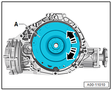
- There is a normal "clicking" in the dual mass flywheel with "LuK" centrifugal pendulum absorber -A-.
- A "clicking" is heard when turning the clutch module -A- approximately every 90º. This noise comes from shifting pendulum masses (centrifugal pendulum absorber) in the dual mass flywheel and is not a fault.
- Secure the transmission on the Engine And Transmission Holder -VAS6095-. Refer to → Chapter "Securing on Engine and Transmission Holder".
- Remove the left flange shaft. Refer to → Chapter "Left Flange Shaft, Removing and Installing".
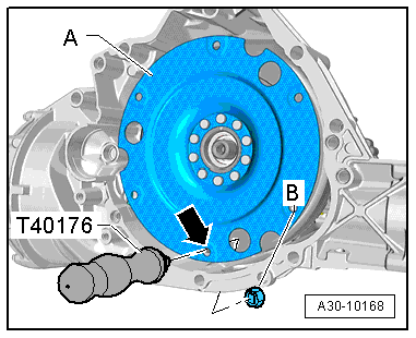
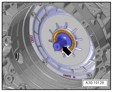
- Attach the Puller - Clutch Module -T40176- to the flywheel -A- with the nut -B--arrow-.
- Turn the Puller - Clutch Module -T40176- upward.
Note
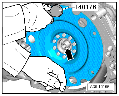
To prevent the flywheel from tilting, counterhold it underneath as shown.
- Remove the flywheel from the input shaft -arrow-. Do not tilt the flywheel when doing this.
Installing
Install in reverse order of removal. At the same time note the following:
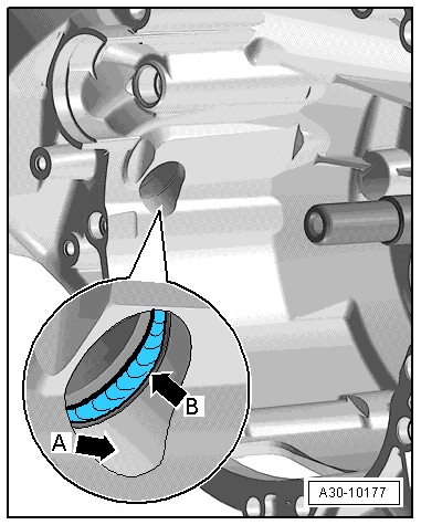
- Always clean the transmission housing in the area where the differential is accessed -arrow A- and the shaft seal -arrow B-.
Note
Replace the shaft seal between the differential and transmission housing -arrow B- if it is damaged.
- Fill the space between the sealing/dust lip halfway with sealing grease. Refer to the Parts Catalog for the correct sealing grease.
- Clean the input shaft -arrow-.
- Lubricate the input shaft splines using Grease for Clutch Disc Shaft Splines -G 000 100-.
- Slide the clutch module onto the input shaft -arrow- carefully without tilting it.
- Remove the Puller - Clutch Module -T40176- from the flywheel -A-.
- Install the left flange shaft. Refer to → Chapter "Left Flange Shaft, Removing and Installing".
READ NEXT:
 Dual Clutch, Removing and Installing
Special tools and workshop equipment required
Shop Crane -VAS6100-
Puller - Input Shaft -T40050-
Pressure Stand -T40099-
Guide Pins - Gearbox -T40288-
Engine Support Bridge - Additional Hooks (2
Input Shaft Double Shaft Seal, Replacing
Special tools and workshop equipment required
Puller - Crankshaft/Power Steering Seal -T20143-
Thrust Piece -T40300-
Clutch, engaging bearing and slave cylinder removed. Refer
to
→ Chap
SEE MORE:
Refrigerant R134a Capacities, Refrigerant Oil and Approved Refrigerant Oils
Approved Refrigerant Oils and Capacities
Note
As PAG (polyalkylene glycol) oil is highly hygroscopic
(attracts water), opened containers are to be immediately
resealed so as to be air-tight.
PAG oil from containers which have been open for a lengthy
period is no longer usable.
Refrige
Introduction
The purpose of this repair manual is to provide service
advisors and technicians with the basic knowledge needed to
ensure professional and competent procedures.
Note
Only the careful study of this documentation, practical
implementation of the information contained, training on A/C
syst
