Audi A4: Overview - Subframe
Overview - Subframe, FWD
 Caution
There is a risk of damaging the threads on the subframe threaded connection to the body.
- The subframe bolts on the body must not be loosened or tightened with an impact wrench.
- Always install all bolts by hand for the first few turns.
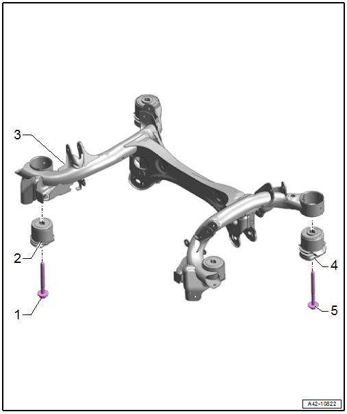
1 - Bolt
- 130 Nm + 180º
- Replace after removing
2 - Front Bonded Rubber Bushing
- For the subframe
3 - Subframe
- Removing and installing. Refer to → Chapter "Subframe, Removing and Installing".
4 - Rear Bonded Rubber Bushing
- For the subframe
5 - Bolt
- 90 Nm + 180º
- Replace after removing
Overview - Subframe, AWD
Caution
There is a risk of damaging the threads on the subframe threaded connection to the body.
- The subframe bolts on the body must not be loosened or tightened with an impact wrench.
- Always install all bolts by hand for the first few turns.
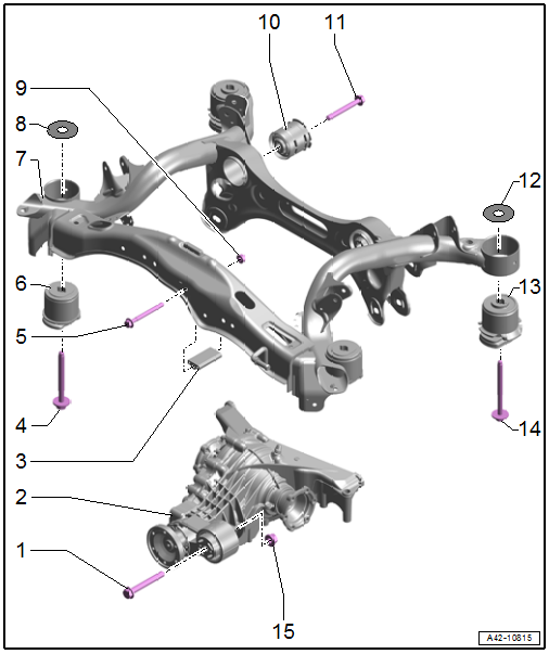
1 - Bolt
- Replace after removing
2 - Rear Final Drive
3 - Stop Buffer
4 - Bolt
- 130 Nm + 180º
- Replace after removing
5 - Bolt
6 - Front Bonded Rubber Bushing
- For the subframe
7 - Subframe
- Securing. Refer to → Chapter "Subframe, Securing".
- Removing and installing. Refer to → Chapter "Subframe, Removing and Installing".
8 - Spacer
- Installed depending on the model
9 - Nut
- 20 Nm
10 - Rear Bonded Rubber Bushing
- For the rear final drive
- Removing and installing. Refer to → Chapter "Rear Bonded Rubber Bushing for Rear Final Drive, Removing and Installing".
- Installation position. Refer to → Fig. "Rear Bonded Rubber Bushings Installation Position for the Rear Final Drive".
11 - Bolt
- Tightening specification. Refer to → Rear Final Drive; Rep. Gr.39; Subframe Mount; Overview - Subframe Mount.
12 - Spacer
- Installed depending on the model
13 - Rear Bonded Rubber Bushing
- For the subframe
14 - Bolt
- 90 Nm + 180º
- Replace after removing
15 - Nut
- Tightening specification. Refer to → Rear Final Drive; Rep. Gr.39; Subframe Mount; Overview - Subframe Mount.
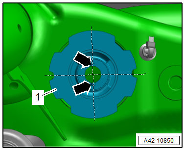
Rear Bonded Rubber Bushings Installation Position for the Rear Final Drive
- The grooves -arrows- on the bonded rubber bushings -1- are at a right angle.
READ NEXT:
 Subframe, Securing
Special tools and workshop equipment required
Torque Wrench 1331 5-50Nm -VAG1331-
Torque Wrench 1332 40-200Nm -VAG1332-
Engine and Gearbox Jack -VAS6931-
Gearbox Support -T40173-
Locating Pins -
Subframe, Removing and Installing
Caution
This procedure contains mandatory replaceable parts.
Refer to component overview and parts catalog prior to
starting procedure.
Mandatory Replacement Parts
Bolt - Bonded Rubber Bu
Stabilizer Bar
Overview - Stabilizer Bar
1 - Bolt
25 Nm + 90º
Replace after removing
Tighten in the curb weight position. Refer to
→ Chapter "Wheel Bearing in Curb Weight Position, Lifting Ve
SEE MORE:
Belt Fastening Detection
Front Passenger Occupant Detection Sensor -G128-, Removing and Installing
Note
The passenger occupant detection sensor is only installed in the
front passenger seat.
Removing
- Unscrew the front passenger seat and tip to the rear with the
wires attached. Refer to
→ Chapter "Fr
Opening navigation
Applies to: vehicles with navigation system
Fig. 140 Route guidance not started
The navigation system directs you to your destination,
around traffic incidents, and on alternative
routes, if desired.
Opening navigation
Applies to: MMI: Press NAVIGATION on the
home screen.
After accessing the na
© 2019-2026 Copyright www.audia4b9.com
