Audi A4: Stabilizer Bar
Overview - Stabilizer Bar
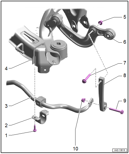
1 - Bolt
- 25 Nm + 90Âş
- Replace after removing
- Tighten in the curb weight position. Refer to → Chapter "Wheel Bearing in Curb Weight Position, Lifting Vehicles with Coil Spring".
- Tighten alternating in stages
2 - Clamp
3 - Stabilizer Bar
- Removing and installing. Refer to → Chapter "Stabilizer Bar, Removing and Installing".
- Do not separate the bonded rubber bushing from the stabilizer bar
4 - Subframe
5 - Nut
- Replace after removing
6 - Front Upper Transverse Link
7 - Bolt
- 40 Nm + 180Âş
- Replace after removing
- Tighten in the curb weight position. Refer to → Chapter "Wheel Bearing in Curb Weight Position, Lifting Vehicles with Coil Spring".
8 - Coupling Rod
- Removing and installing. Refer to → Chapter "Coupling Rod, Removing and Installing".
9 - Bolt
- 40 Nm + 180Âş
- Replace after removing
- Tighten in the curb weight position. Refer to → Chapter "Wheel Bearing in Curb Weight Position, Lifting Vehicles with Coil Spring".
10 - Nut
- Replace after removing
Stabilizer Bar, Removing and Installing
Special tools and workshop equipment required
- Torque Wrench 1331 5-50Nm -VAG1331-
 Caution
This procedure contains mandatory replaceable parts. Refer to component overview and parts catalog prior to starting procedure.
Mandatory Replacement Parts
- Bolt/Nut - Coupling Rod to Stabilizer Bar
- Bolt - Stabilizer Bar Clamp to Subframe
Removing
- Before starting the procedure, determine the curb weight position. Refer to → Chapter "Wheel Bearing in Curb Weight Position, Lifting Vehicles with Coil Spring".
- Equipped on some models: Remove the right diagonal brace. Refer to → Body Exterior; Rep. Gr.66; Underbody Trim Panel; Diagonal Braces, Removing and Installing.
- Remove the left and right bolts -arrows-.
- Disconnect the left and right threaded connection -1- and remove the stabilizer bar -2-.
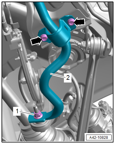
 Note
Note
The installation position is shown for the AWD equipment version.
Installing
Install in reverse order of removal.
Tightening Specifications
- Refer to → Chapter "Overview - Stabilizer Bar"
- Refer to → Body Exterior; Rep. Gr.66; Underbody Trim Panel; Overview - Underbody Trim Panels.
Coupling Rod, Removing and Installing
Special tools and workshop equipment required
- Torque Wrench 1331 5-50Nm -VAG1331-
Caution
This procedure contains mandatory replaceable parts. Refer to component overview and parts catalog prior to starting procedure.
Mandatory Replacement Parts
- Bolt/Nut - Coupling Rod to Front Upper Transverse Link
- Bolt/Nut - Coupling Rod to Stabilizer Bar
Removing
- Before starting the procedure, determine the curb weight position. Refer to → Chapter "Wheel Bearing in Curb Weight Position, Lifting Vehicles with Coil Spring".
- Disconnect the connectors -1 and 3- and remove the coupling rod -2-.
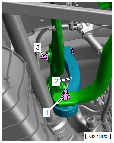
Note
The installation position is shown for the AWD equipment version.
Installing
Install in reverse order of removal.
Tightening Specifications
- Refer to → Chapter "Overview - Stabilizer Bar"
READ NEXT:
 Overview - Transverse Link
Upper Transverse Link
1 - Wheel Bearing Housing
2 - Bolt
70 Nm + 180Âş
Replace after removing
3 - Front Upper Transverse Link
Removing and installing. Refer to
â†
Upper Transverse Link, Removing and Installing
Front Upper Transverse Link, Removing and Installing
Special tools and workshop equipment required
Torque Wrench 1332 40-200Nm -VAG1332-
Caution
This procedure contains mandatory replaceab
SEE MORE:
Overview - Antenna Systems
Overview - Antenna Systems, Sedan, USA
The antenna systems consist of window antennas, a Roof
Antenna - R216- and bumper antennas.
Window Antennas
Antenna -R11- (AM/FM1)/TV Antenna 1 -R55- (TV1) to the
Antenna Amplifier -R24- at the top of the right D-pillar
TV Antenna 2 -R56- (TV2) to the TV A
Repair Information
Guidelines for Clean Working Conditions
Thoroughly clean connection points and their surrounding
areas with engine or brake cleaner before loosening and allow
the cleaned connection points to dry completely.
Clean the transmission and transmission components using
Cleaning Solution -D 009 401
