Audi A4: Rear Axle Camber, Adjusting
 Caution
This procedure contains mandatory replaceable parts. Refer to component overview and parts catalog prior to starting procedure.
Mandatory Replacement Parts
- Nut - for Adjusting Bolt
Procedure
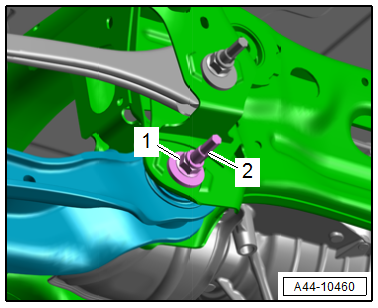
- Remove the nut -1- from the subframe/rear lower transverse link threaded connection and install the new nut all the way.
- Adjust the camber by rotating the adjusting bolt -2-.
 Note
Note
To turn the adjusting bolt, turn the hex head at the "top of the bolt".
- Axle alignment specified values. Refer to → Chapter "Axle Alignment Specified Values".
Note
- The maximum adjustment range is 135º to left or right of center position.
- Do not rotate the adjusting bolt -2- further once the end position has been reached or the components will be damaged.
- For clarity the rear wheel is not shown.
- Tighten the nut and check the camber value again. Refer to → Chapter "Axle Alignment Specified Values".
Tightening Specifications
- Refer to → Chapter "Overview - Transverse Link"
Rear Axle Toe, Adjusting
Special tools and workshop equipment required
- Fine tooth ratchet, commercially available
Caution
This procedure contains mandatory replaceable parts. Refer to component overview and parts catalog prior to starting procedure.
Mandatory Replacement Parts
- Nut - for Adjusting Bolt
Procedure
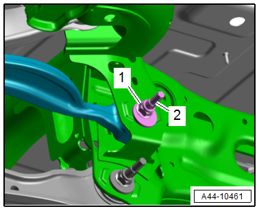
- Remove the nut -1- from the threaded connection for the tie rod/subframe, and install the new nut all the way.
- Adjust the toe by turning the eccentric bolt -2-.
Note
To turn the eccentric bolt, turn the hex head at the "top of the bolt".
- Axle alignment specified values. Refer to → Chapter "Axle Alignment Specified Values".
Note
- The maximum adjustment range is 90º to left or right of center position.
- The geometric drive axle is automatically changed when individual toe settings are changed.
- Tighten the nut and check the toe value again. Refer to → Chapter "Axle Alignment Specified Values".
Tightening Specifications
- Refer to → Chapter "Overview - Transverse Link"
READ NEXT:
 Front Axle Camber, Centering
Note
Camber cannot be adjusted.
Camber can be centered evenly within specified tolerance
range by shifting subframe.
Procedure
- Remove the noise insulation. Refer to
→ Body
Dynamic Steering
Overview - Dynamic Steering
1 - Steering Gear
with Power Steering Control Module -J500-
2 - Electromechanical Power Steering Motor -V187-
Steering column component
Do not di
Adaptive Cruise Control (ACC)
Adaptive Cruise Control (ACC), Adjusting
Special tools and workshop equipment required
Vehicle Diagnostic Tester
Wheel Alignment Computer
Screwdriver with T-bar -VAS272001-, not illustrated
Setti
SEE MORE:
Checking Pressures for Vehicles with Restrictor and Reservoir (with
Internally Regulated Compressor)
General Information
Note
Connect the A/C service station. Refer to
→ Chapter "A/C Service Station, Connecting".
Observe the test requirements. Refer to
→ Chapter "Pressures, Checking".
- With the ignition switched off, check the pressure in the
refrigerant circuit (u
Refrigerant Circuit, General Precautions
General Information
Ensure absolute cleanliness when working.
Wear safety goggles and gloves when working with refrigerant
and nitrogen.
Workshop extraction systems are to be switched on.
Use the service station to discharge the refrigerant
circuit, only then open screw connections and replac
