Audi A4: Center Differential
Overview - Center Differential
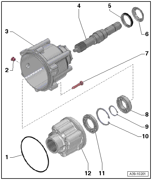
1 - O-Ring
- Replacing
- Coat with transmission fluid
2 - Plug
- For the hole for checking and filling
- For the transmission fluid inside the transfer case
- Tightening Specification.
3 - Center Differential Housing
- Removing and installing. Refer to → Chapter "Center Differential, Removing and Installing".
4 - Transmission Output Shaft With Splines
- Removing and installing. Refer to → Chapter "Transmission Output Shaft Seal, Replacing".
- Replace the seal when replacing the transmission output shaft with splines
5 - Seal
- For the transmission output shaft with splines
- Replacing. Refer to → Chapter "Transmission Output Shaft Seal, Replacing".
6 - Dust Ring
- cannot be removed without being destroyed
7 - Bolt
- Replacing
- Tightening specification and sequence. Refer to → Fig. "Center Differential Housing - Tightening Specification and Sequence".
8 - Ball Bearing
- For the transmission output shaft with splines
- Replacing. Refer to → Chapter "Transmission Output Shaft Ball Bearing, Replacing".
9 - Circlip
- For the transmission output shaft with splines
10 - Circlip
- For the ball bearing on the transmission output shaft with splines
11 - Ball Bearing
- For the center differential
- Replacing. Refer to → Chapter "Center Differential Ball Bearing, Replacing".
12 - Center Differential
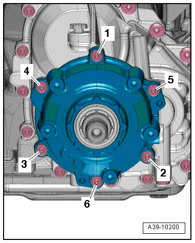
Center Differential Housing - Tightening Specification and Sequence
 Note
Note
Replace the bolts that were tightened with an additional turn.
- Tighten the bolts in three steps in the sequence shown:
.png)
Center Differential, Removing and Installing
Removing
- The transmission is installed.
 Caution
Risk of damaging the transmission.
Do not start or tow the vehicle when the center differential is removed or when the gear oil has been drained.
Note
- General repair instructions. Refer to → Chapter "General Repair Information".
- Guidelines for clean working conditions. Refer to → Chapter "Guidelines for Clean Working Conditions".
- Remove the driveshaft. Refer to → Rear Final Drive; Rep. Gr.39; Driveshaft; Driveshaft, Removing and Installing.
- Drain the gear oil from the transfer case.
- Remove the bolts from the center differential housing in the following sequence: -6 to 1-.
Caution
Transmission components could be damaged.
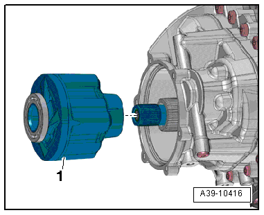
Carefully remove the center differential housing from the transmission toward the rear. Otherwise the center differential could fall out of the transmission.
- Secure the center differential -1- so it does not fall out or remove it toward the rear from the input shaft.
Installing
Install in the reverse order of removal while noting the following:
Note
Replace the center differential housing O-ring.
If the center differential -1- was removed:
- Position the center differential on the input shaft splines. Rotate the center differential slightly when doing this.
- Make sure the center differential can be turned by hand.
- Install the housing with the transmission output shaft with splines installed and a new O-ring onto the center differential. Rotate the housing slightly if necessary.
- Install the driveshaft. Refer to → Rear Final Drive; Rep. Gr.39; Driveshaft; Driveshaft, Removing and Installing.
- Fill the transmission fluid and check the level. Refer to → Chapter "Transmission Fluid, Draining and Filling".
Tightening Specifications
- Refer to → Fig. "Center Differential Housing - Tightening Specification and Sequence"
Transmission Output Shaft Seal, Replacing
Special tools and workshop equipment required
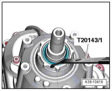
- Puller - Crankshaft/Power Steering Seal -T20143/1-
- Seal Installer - Output Shaft -T40239-
- Sealing Grease -G 052 128 A1-
Procedure
Note
- General repair instructions. Refer to → Chapter "General Repair Information".
- Guidelines for clean working conditions. Refer to → Chapter "Guidelines for Clean Working Conditions".
- Remove the driveshaft. Refer to → Rear Final Drive; Rep. Gr.39; Driveshaft; Driveshaft, Removing and Installing.
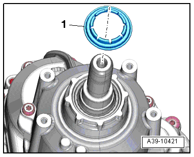
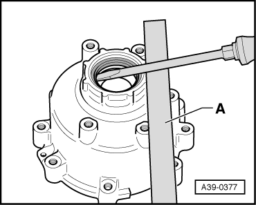
- Pry off the dust ring -1-.
Note
The dust ring cannot be removed without destroying it.
- Remove the seal for the transmission output shaft with splines.
- Clean the running and sealing surface.
- Coat outer edge of the seal with gear oil.
- Mount the Seal Installer - Output Shaft - Guide Sleeve 1 -T40239/1-, -1- on the transmission output shaft.
- Fill the space between the sealing/dust lip halfway with Sealing Grease -G 052 128 A1-.
- Install the seal -2- over the guide sleeve -1- and onto the transmission output shaft.
- Installed position: The open side of the seal faces the transmission housing.
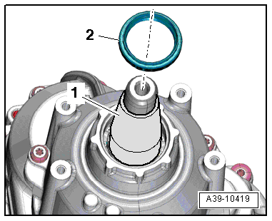
- Install the seal all the way using the Seal Installer - Output Shaft -T40239-, -1-. Do not tilt the seal.
Note
Remove the Seal Installer - Output Shaft - Guide Sleeve 1 -T40239/1- from the seal carefully so that the sealing lip does not fold over.
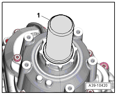
- Install a new dust ring -1-.
- Install the driveshaft. Refer to → Rear Final Drive; Rep. Gr.39; Driveshaft; Driveshaft, Removing and Installing.
Transmission Output Shaft Ball Bearing, Replacing
Special tools and workshop equipment required
- Press Plate -VW401-
- Press Plate -VW402-
- Press Piece - Rod -VW409-
- Press Piece - Multiple Use -VW412-
- Press Piece - 60mm -VW415A-
- Press Piece - Front Control Arm -2040-
Procedure
- Remove the center differential housing. Refer to → Chapter "Center Differential, Removing and Installing".
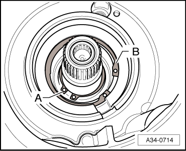
- Remove the locking ring -A- on the transmission output shaft with splines and the ball bearing circlip -B-.
- Remove the transmission output shaft from the center differential housing using the Press Piece - Rod -VW409-.

- Pry out the seal.
Note
To protect the housing lay for example an extractor lever -A- underneath.
- Remove the transmission output shaft ball bearing with splines.
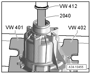
- Install the transmission output shaft ball bearing with splines.
- The shoulder on the Press Piece - 60mm -VW415A--arrow- faces the Press Piece - Multiple Use -VW412-.
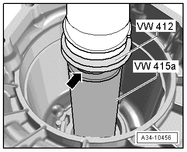
- Install the ball bearing circlip -B-.
Note
Ignore -A-.
- Install the transmission output shaft into the center differential housing using the Press Piece - Multiple Use -VW412-.
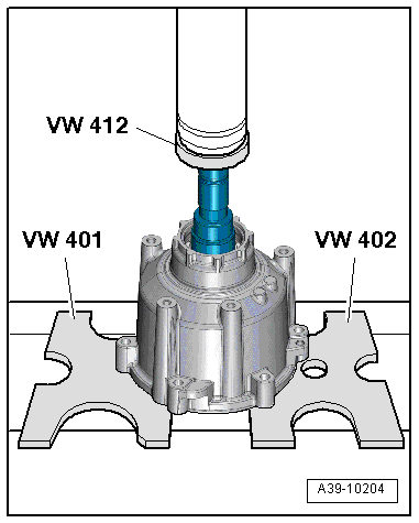
- Install the locking ring -arrow- into the groove in the transmission output shaft.
- Install the center differential housing. Refer to → Chapter "Center Differential, Removing and Installing".
- Install the seal for the transmission output shaft with splines. Refer to → Chapter "Transmission Output Shaft Seal, Replacing".
- Fill the transmission fluid and check the level. Refer to → Chapter "Transmission Fluid, Draining and Filling".
Center Differential Ball Bearing, Replacing
Special tools and workshop equipment required
- Press Plate -VW401-
- Press Plate -VW402-
- Press Piece - Multiple Use -VW412-
- Press Piece - Bushing - 50mm Diameter -VW432-
- Bearing Installer - Carrier Bearing -3350-
- Splitter VAS251411 -VAS251411-
Procedure
- Remove the center differential housing. Refer to → Chapter "Center Differential, Removing and Installing".
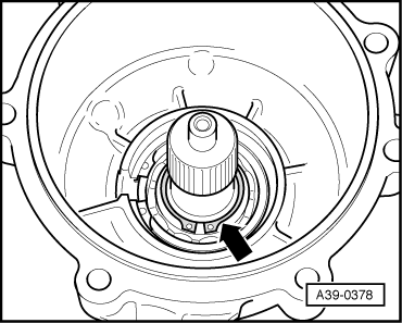
- Remove the center differential -1- from the output shaft.
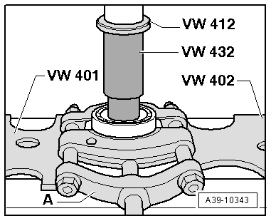
- Removing the ball bearing from the center differential
A - Splitter VAS251411 -VAS251411-
- The Press Piece - Bushing - 50mm Diameter -VW432- faces the ball bearing.
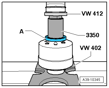
- Installing the ball bearing onto the center differential
READ NEXT:
 Special Tools
Special tools and workshop equipment required
Seal Installer - Final Drive/Gearbox -T10337-
Puller - Crankshaft/Power Steering Seal -T20143/1-
Seal Installer - Flange Shaft -T40163-
Seal Install
SEE MORE:
Rear Lid, Adjusting
Adjustment Dimensions
Adjustment Dimensions, Sedan
A -
Rear Lid to Top of Side Panel
Gap dimension = 3.5 mm
B -
Rear Lid to Side Panel
Gap dimension = 3.5 mm
C -
Rear Lid to Side Panel
Gap dimension = 3.5 mm
D -
Rear Lid to Rear Lid End
Gap dimensi
Suspension
Adaptive dampers
Applies to: vehicles with suspension control
The adaptive dampers are an electronically-controlled
damping system. The firmness of the suspension
will adapt to the driving conditions and
the driving situation. The settings depend on the
selected Audi drive select* mode.
Ground clear
