Audi A4: Selector Mechanism
Audi A4 (B9) 2016-2026 Service Manual / Transmission / 7-Speed Dual Clutch Transmission 0CJ, 0CK, 0CL / Controls, Housing / Selector Mechanism
Overview - Selector Mechanism
Selector Mechanism in the Vehicle Interior
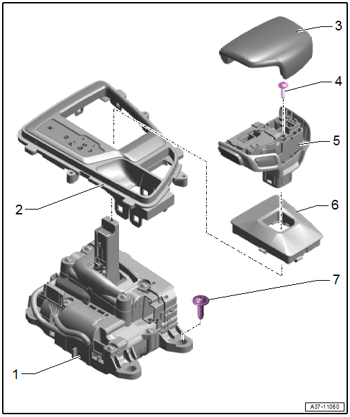
1 - Selector Mechanism
- With the following integrated components:
- Selector Lever -E313-
- Selector Lever Position Sensor -G727-
- Transverse Selector Lever Lock Sensor -G868-
- Selector Lever Sensor System Control Module -J587-
- Shift Lock Solenoid -N110-
- Transverse Selector Lever Lock Motor -V577-
- The components cannot be replaced separately if faulty.
- Removing and installing. Refer to → Chapter "Selector Mechanism, Removing and Installing".
2 - Selector Lever Transmission Range Display -Y5-
- Removing and installing. Refer to → Electrical Equipment; Rep. Gr.96; Lamps; Component Location Overview - Lamps in Center Console.
3 - Selector Lever Handle, Upper Section
- Removing and installing. Refer to → Chapter "Selector Lever Handle, Removing and Installing".
4 - Bolt
- 3.2 Nm
- Not available separately
5 - Selector Lever Handle, Lower Section
- With the following integrated components:
- Selector Lever Release Button -E681-
- Parking Lock Button -E816-
- The components cannot be replaced separately if faulty.
- Removing and installing. Refer to → Chapter "Selector Lever Handle, Removing and Installing".
6 - Selector Lever Boot
- Removing and installing. Refer to → Chapter "Selector Lever Boot on Selector Lever Handle, Disconnecting and Assembling".
7 - Bolt
- 8 Nm
Gearshift Mechanism on Transmission
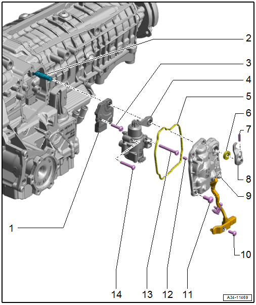
1 - Parking Lock Sensor -G747-
- Removing and installing. Refer to → Chapter "Parking Lock Solenoid -N486-/Parking Lock Sensor -G747-, Removing and Installing".
2 - Shaft
- For the parking lock
3 - Bolt
- 3 Nm +90º
- Replace after removing
4 - Parking Lock Solenoid -N486-
- Electro-hydraulic part
- Removing and installing. Refer to → Chapter "Parking Lock Solenoid -N486-/Parking Lock Sensor -G747-, Removing and Installing".
5 - Seal
- Replace after removing
6 - Seal
- For the parking lock shaft
- Replacing. Refer to → Chapter "Parking Lock Shaft Seal, Replacing".
7 - Spring Pin
8 - Lever
- For the parking lock
- Removing and installing. Refer to → Chapter "Parking Lock Shaft Seal, Replacing".
9 - Cover
- For the parking lock
- With electric wiring harness
10 - Bolt
- 3 Nm +90º
- Replace after removing
11 - Bolt
- 8 Nm +60º
- Replace after removing
12 - Alignment Pin
- Quantity: 2
13 - Bolt
- 3 Nm +45º
- Replace after removing
14 - Bolt
- 3 Nm +90º
- Replace after removing
Overview - Parking Lock Emergency Release
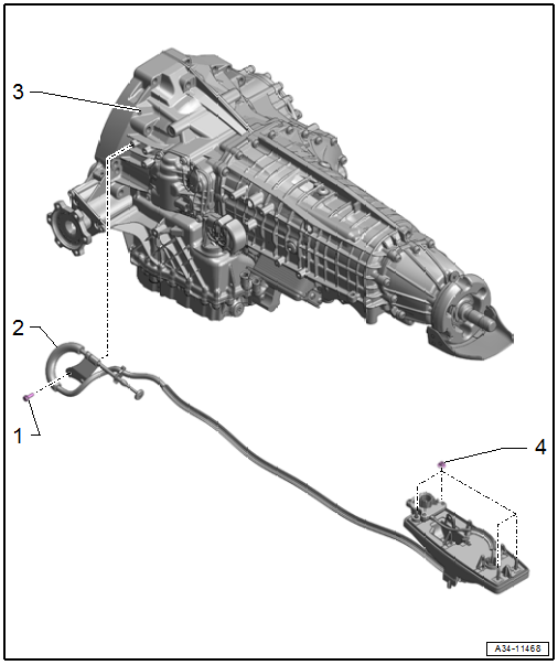
1 - Emergency Release Cable
- For the parking lock
- Do not bend or kink
- Removing and installing. Refer to → Chapter "Parking Lock Emergency Release Cable, Removing and Installing".
2 - Nut
- 4 Nm
- Quantity: 2
3 - Transmission
4 - Nut
- 8 Nm
READ NEXT:
 Gearshift Mechanism, Checking
WARNING
Risk of injury and accident by accidentally engaging
a selector lever position with the engine running.
Before working with the engine running, move the
transmission into "P" and
Selector Lever Handle, Removing and Installing
Note
Both the selector lever handle and the selector lever boot
are removed together.
Special tools and workshop equipment required
Trim Removal Wedge -3409-
Torque Wrench 1410 - VAG1410-
Parking Lock Emergency Release Cable, Removing and Installing
Removing
WARNING
There is a risk of an accident from the vehicle
starting to roll.
Pull the parking brake button to activate the
electro-mechanical parking brake.
- Remove the selector
SEE MORE:
Safety Precautions
Safety Precautions when Working on Vehicles with Start/Stop System
There is a risk of injury due to the engine starting
unexpectedly.
The engine can start unexpectedly on vehicles with an activated
Start/Stop System. A message in the instrument cluster indicates
whether the Start/Stop System is a
Wheel Bearing Unit, Removing and Installing
Wheel Bearing Unit, Removing and Installing, FWD
Special tools and workshop equipment required
Puller - Grease Cap -VW637/2-
Camshaft Installer Kit - Sleeve -3241/4- from the Seal
Installer - Camshaft Installer Kit -3241-
Torque Wrench 1332 40-200Nm -VAG1332-
Torque Wrench 1410 -VAG1410-
&n
© 2019-2026 Copyright www.audia4b9.com
