Audi A4: Differential
Overview - Differential
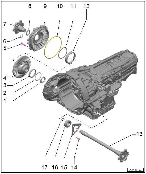
1 - Left Flange Shaft Seal
- Replacing. Refer to → Chapter "Left Seal, Replacing".
2 - Shim
- Behind the taper roller bearing outer race
3 - Taper Roller Bearing Outer Race
4 - Front Differential
5 - Bolt
- Tightening specification and sequence. Refer to → Fig. "Final Drive Cover - Tightening Specification and Sequence".
6 - Circlip
- Replacing
7 - Right Flange Shaft
- Removing and installing. Refer to → Chapter "Right Flange Shaft, Removing and Installing".
8 - Right Flange Shaft Seal
- Replacing. Refer to → Chapter "Right Seal, Replacing".
9 - Final Drive Cover
- Removing and installing. Refer to → Servicing - 7-Speed Dual Clutch Transmission 0CJ, 0CK, 0CL; Rep. Gr.39; Gaskets; Left Gasket, Replacing.
10 - O-Ring
- Replace after removing
11 - Shim
- Behind the taper roller bearing outer race
12 - Taper Roller Bearing Outer Race
13 - Left Flange Shaft
- Removing and installing. Refer to → Chapter "Left Flange Shaft, Removing and Installing".
14 - Bolt
- Tightening specification 10 Nm + 90º
- Quantity: 3
15 - Gear Carrier
- Attached to the left flange shaft with the bearing -16- and the circlip -17-
16 - Bearings
- For the left flange shaft
17 - Circlip
- For the left flange shaft bearing
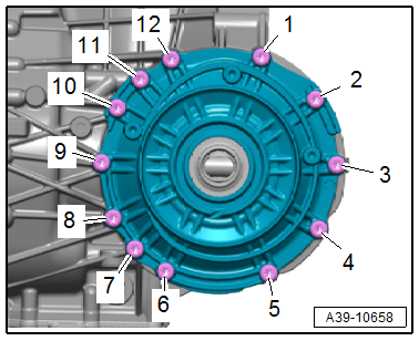
Final Drive Cover - Tightening Specification and Sequence
- Tighten the bolts in steps according to the specified sequence:
.png)
Left Flange Shaft, Removing and Installing
Special tools and workshop equipment required
- Sealing Grease. Refer to the Parts Catalog.
Removing
- The transmission is installed.
- Drain the transmission fluid. Refer to → Chapter "Transmission Fluid, Draining and Filling".
- Remove the left drive axle. Refer to → Suspension, Wheels, Steering; Rep. Gr.40; Drive Axle; Drive Axle, Removing and Installing.
- Remove the left drive axle heat shield. Refer to → Suspension, Wheels, Steering; Rep. Gr.40; Drive Axle; Drive Axle Heat Shield, Removing and Installing.
- Remove the left shock absorber fork. Refer to → Suspension, Wheels, Steering; Rep. Gr.40; Suspension, Upper Control Arm; Tower Brace, Removing and Installing.
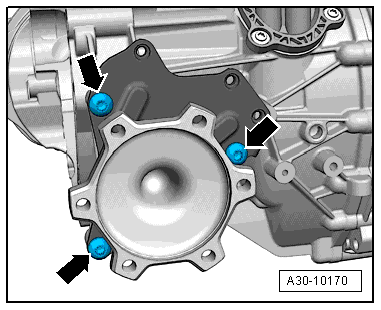
- Remove the bolts -arrows- from the flange shaft mounting bracket.
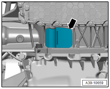
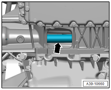
- Remove the lower cover -arrow- from the transmission.
 WARNING
Risk of damaging the seal between the final drive and the transmission housing when removing the flange shaft.
- If the flange shaft -arrow- is not held in a central position, the seal on the flange shaft spline will be damaged.
- A seal must be replaced if it is damaged.
- To avoid damaging the seal, support and guide the flange shaft out of the opening in the transmission.
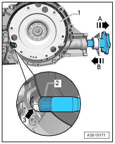
- Remove the left flange shaft -2- from the transmission in direction of -arrow A-.
 Note
Note
Ignore -1, 3 and B-.
Installing
Install in the reverse order of removal while noting the following:
Note
Replace bolts that were tightened with an additional turn after removing them.
WARNING
Risk of damaging the seal between the final drive and the transmission housing when installing the flange shaft.
- If the flange shaft -arrow- is not held in a central position, the seal on the flange shaft spline will be damaged.
- A seal must be replaced if it is damaged.
- To avoid damaging the seal when inserting the flange shaft, support and guide the flange shaft into the opening in the transmission.
- Slide the left flange shaft -2- into the transmission in direction of -arrow B-. When doing this, insert the flange shaft centrally into the seal on the front differential -arrow 3-.
- Install the shock absorber fork. Refer to → Suspension, Wheels, Steering; Rep. Gr.40; Suspension, Upper Control Arm; Shock Absorber Fork, Removing and Installing.
Tightening Specification
- Refer to → Chapter "Overview - Differential"
- Refer to → Suspension, Wheels, Steering; Rep. Gr.40; Drive Axle; Overview - Drive Axle.
- Refer to → Suspension, Wheels, Steering; Rep. Gr.40; Drive Axle; Drive Axle Heat Shield, Removing and Installing.
Right Flange Shaft, Removing and Installing
Special tools and workshop equipment required
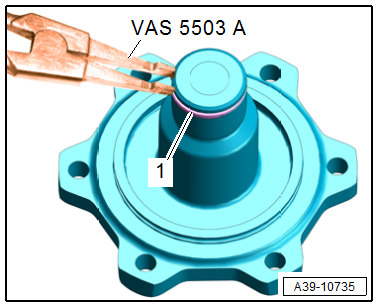
- Circlip Pliers -VAS5503A-
- Used Oil Collection and Extraction Unit -SMN372500-
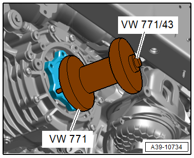
- Slide Hammer Set -VW771- with Slide Hammer Set - Bolt -VW771/43-
- Sealing Grease -G 052 128 A1-
Removing
- Remove the right drive axle. Refer to → Suspension, Wheels, Steering; Rep. Gr.40; Drive Axle; Drive Axle, Removing and Installing.
- Remove the right drive axle heat shield. Refer to → Suspension, Wheels, Steering; Rep. Gr.40; Drive Axle; Drive Axle Heat Shield, Removing and Installing.
- Place the Used Oil Collection and Extraction Unit -SMN372500- under the transmission.
- Place the Slide Hammer Set -VW771- with Slide Hammer Set - Bolt -VW771/43- on the flange shaft, as shown.
- Remove flange shaft.
Installing
Install in the reverse order of removal while noting the following:
Note
Replace the circlip after removal.
- Insert the circlip -1- with the Circlip Pliers -VAS5503A-.
- Check the right flange shaft seal for damage and replace if necessary. Refer to → Chapter "Right Seal, Replacing".
- Fill the space between the sealing/dust lip halfway with Sealing Grease -G 052 128 A1-.
- Insert the right flange shaft.
- Fill the transmission fluid and check the level. Refer to → Chapter "Transmission Fluid, Draining and Filling".
Tightening Specifications
- Refer to → Chapter "Overview - Differential"
- Refer to → Suspension, Wheels, Steering; Rep. Gr.40; Drive Axle; Overview - Drive Axle.
- Refer to → Suspension, Wheels, Steering; Rep. Gr.40; Drive Axle; Drive Axle Heat Shield, Removing and Installing.
READ NEXT:
 Center Differential
Overview - Center Differential
1 - O-Ring
Replacing
Coat with transmission fluid
2 - Plug
For the hole for checking and filling
For the transmission fluid inside the transf
Special Tools
Special tools and workshop equipment required
Seal Installer - Final Drive/Gearbox -T10337-
Puller - Crankshaft/Power Steering Seal -T20143/1-
Seal Installer - Flange Shaft -T40163-
Seal Install
SEE MORE:
Sliding Sunroof
Overview - Sliding Sunroof
Overview - Sliding Sunroof, Sedan
1 -
Screw
3 Nm
Quantity: 2
2 -
Sunroof Motor -V1-
Removing and installing. Refer to
→ Chapter "Sunroof Motor -V1-, Removing and Installing".
Perform the adaptation after installing. Refer to
→ Chap
Window Guide, Removing and Installing
Removing
- Remove the door window. Refer to
→ Chapter "Front Door Window, Removing and Installing".
- Remove the B-pillar trim. Refer to
→ Chapter "B-Pillar Door Trim, Removing and Installing, Front".
- Remove the A-pillar trim. Refer to
→ Chapter "A-Pillar Tri
