Audi A4: Driver/Front Passenger Seat Adjustment Control Head -E470-/-E471-, Removing and Installing
Special tools and workshop equipment required
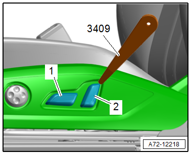
- Trim Removal Wedge -3409-
Removing
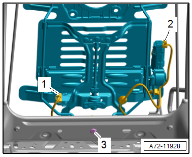
- Carefully pry the actuators -1 and 2- from the retainer using the -3409-.
- Remove the seat side trim on the side sill side. Refer to → Chapter "Seat Side Trim on Side Sill Side, Removing and Installing".
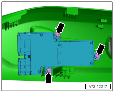
- Remove the bolts -arrows-.
- Remove the control head from the seat side trim on the side sill side.
Installing
Install in reverse order of removal.
Installation instructions: For example tightening specifications, replacing components. Refer to → Chapter "Overview - Seat Pan, Power Seat Adjustment Actuator/Switch".
Driver and Front Passenger Seat Lumbar Support Adjustment Switch -E176-/-E177-, Removing and Installing
Removing
- Remove the seat side trim on the side sill side. Refer to → Chapter "Seat Side Trim on Side Sill Side, Removing and Installing".
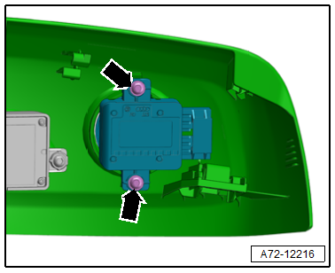
- Remove the screws -arrows- and remove the switch module.
Installing
Install in reverse order of removal and note the following:
Installation instructions: For example tightening specifications, replacing components. Refer to → Chapter "Overview - Seat Pan, Power Seat Adjustment Actuator/Switch".
Lumbar Support Adjustment Motors -V125-/-V126-/-V129-/-V130-, Removing and Installing
Special tools and workshop equipment required
- Pop Rivet Pliers -VAG1753B-
- Engine/Transmission Holder - Seat Repair Fixture -VAS6136-
- Hand drill
- Protective Eyewear
Removing
 WARNING
Risk of injury due to involuntary deployment.
- Pay attention to the safety precautions when working with pyrotechnic components. Refer to → Chapter "Safety Precautions when Working with Pyrotechnic Components".
- Before handling pyrotechnic components (For example, disconnecting the connector), the person handling it must "discharge static electricity". For example, this can be done by briefly touching the door striker.
- Remove the front seat. Refer to → Chapter "Front Seat, Removing and Installing".
- Fasten the front seat on the -VAS6136-. Refer to → Chapter "Front Seat, Mounting on Fixture for Seat Repair".
- Remove the backrest seat cover and cushion. Refer to → Chapter "Backrest Cover and Cushion, Removing and Installing".
Schukra Lumbar Support
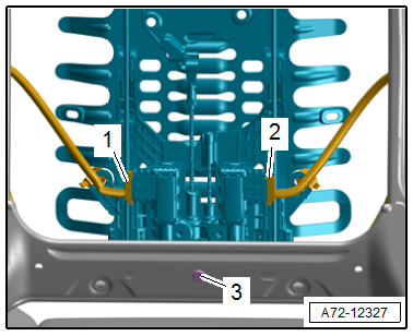
- Detach the connectors -1 and 2- at the lumbar support forward/back and height adjustment motors.
- Cut through the cable tie and free up the wiring harness on the lumbar support.
WARNING
Risk of eye injury.
Wear protective eyewear!
- Drill out the rivet -3-.
Brose Lumbar Support
- Detach the connectors -1 and 2- at the lumbar support forward/back and height adjustment motors.
- Cut through the cable tie and free up the wiring harness on the lumbar support.
WARNING
Risk of eye injury.
Wear protective eyewear!
- Drill out the rivet -3-.
Continued for All Versions
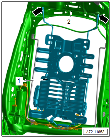
- Move the lower lumbar support -1- forward, pivot it out of the backrest frame, disengage it from the backrest frame -2--arrows- and remove it.
Installing
WARNING
Risk of injury due to involuntary deployment.
- Pay attention to the safety precautions when working with pyrotechnic components. Refer to → Chapter "Safety Precautions when Working with Pyrotechnic Components".
- Before handling pyrotechnic components (For example, connecting a connector), the person handling it must "discharge static electricity". For example, this can be done by briefly touching the door striker.
- Follow all the instructions when installing the front seat. Refer to → Chapter "Front Seat, Removing and Installing".
- Engage the lumbar support -1- at the top in the backrest frame -2--arrows-, pivot the bottom toward the rear and insert in the backrest frame.
- Rivet the lumbar support to the backrest frame.
Further installation is the reverse order of removal.
Installation instructions: For example tightening specifications, replacing components. Refer to → Chapter "Overview - Front Backrest, Lumbar Support".
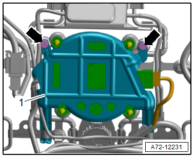
Seat Functions Control Module, Removing and Installing
Removing
- Switch off the ignition.
- Unscrew the front seat and tip to the rear with the wires attached. Refer to → Chapter "Front Seat, Removing and Installing".
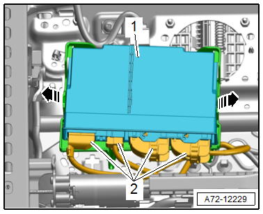
- Release retaining tabs -arrows-.
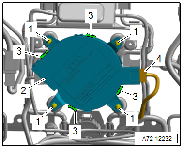
- Remove the control module -1- from the bracket.
- Release the connector safety catch and disconnect the connectors -2-.
Installing
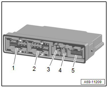
- If the control module was replaced, follow the sequence when connecting the connectors.
- First connect the connector -5- (coding connector), then connect the other connectors -1 to 4-.
Further installation is the reverse order of removal.
Seat Cushion Fan, Removing and Installing
Special tools and workshop equipment required
- Pop Rivet Nut Pliers -VAS5073A-
- Engine/Transmission Holder - Seat Repair Fixture -VAS6136-
- Mini-grinder, commercially available
- Protective Eyewear
Removing
WARNING
Risk of injury due to involuntary deployment.
- Pay attention to the safety precautions when working with pyrotechnic components. Refer to → Chapter "Safety Precautions when Working with Pyrotechnic Components".
- Before handling pyrotechnic components (For example, disconnecting the connector), the person handling it must "discharge static electricity". For example, this can be done by briefly touching the door striker.
- Remove the front seat. Refer to → Chapter "Front Seat, Removing and Installing".
- Fasten the front seat on the -VAS6136-. Refer to → Chapter "Front Seat, Mounting on Fixture for Seat Repair".
WARNING
Risk of eye injury.
Wear protective eyewear!
- Carefully separate the pop rivets -arrows- using a mini grinder.
- Remove the cover -1- for the fan.
- Disconnect the connector -4-.
- Disengage the tabs -3- on the seat cushion fan and remove the fan -2-.
- Spray the rubber fasteners -1- for the elastic fan bracket with silicone-free lubricating spray and remove the fan from the rubber fasteners.
Installing
Install in reverse order of removal.
READ NEXT:
 Rear Seats
Overview - Bench Seat/Single Seat
1 - Grommets
For securing the rear bench seat
Clipped into the vehicle floor
Replace each time the bench seat is removed
2 - Bench Seat
Re
Bench Seat/Single Seat, Removing and Installing
Removing
- Move the front seats all the way forward.
- Unclip the child seat anchor guides (quantity: four)
-1- from anchorages. Refer to
→ Chapter "Lower Child Seat Anchor Guide, Rem
Rear Seat Backrest, Removing and Installing
Rear Seat Backrest, Removing and Installing, Fixed Rear Seat Backrest
Removing
- Remove the screws -1- in the
luggage compartment.
- Remove the bench seat. Refer to
→ Chapter "Bench
SEE MORE:
Fan Shroud, Removing and Installing
Removing
- Remove the front noise insulation. Refer to
→ Body Exterior; Rep. Gr.66; Noise Insulation; Overview - Noise
Insulation.
- Remove the charge air cooler. Refer to
→ Chapter "Charge Air Cooler, Removing and Installing".
WARNING
There is a risk of
Seat Belt Height Adjuster, Removing and Installing
Caution
This procedure contains mandatory replaceable parts.
Refer to component overview and parts catalog prior to
starting procedure.
Mandatory Replacement Parts
Bolt - Seat Belt Guide to Seat Belt Height Adjuster (Replace
bolt if it was removed because of an accident when the seat b
