Audi A4: Engine, Installing
Special tools and workshop equipment required
- Clutch Module Assembly Aid -T40169-
- Clutch Module Transportation Lock -T40170-
- as well as when removing with listed special tools
- Engine Support Bridge - Spindle -10-222A/11-
- Shop Crane -VAS6100-
- Engine Sling -2024A-
- Torque Wrench 1332 Insert - Ring Wrench - 16mm -VAG1332/14-
- Wrench - 21mm -T40263-,
- Adapter -T40314-
Tightening Specifications
 Note
Note
- The tightening specifications only apply to lightly greased, oiled, phosphated or blackened nuts and bolts.
- Additional lubricants, such as engine or transmission oil are permissible, although lubricants containing graphite are not.
- Do not use any ungreased parts.
- Tightening specification tolerance: +-15%.
.png)
- Refer to → Chapter "Overview - Subframe Mount"
- Engine to transmission. Refer to → Transmission; Rep. Gr.34; Transmission, Removing and Installing; Transmission Tightening Specifications.
Procedure
Note
- Replace the bolts that were tightened with an additional turn after removing them.
- Replace the self-locking nuts and bolts, gaskets, seals and O-rings after removing.
- In the drive plate on vehicles with a manual transmission a needle bearing is installed. Refer to → Servicing - 4-Cylinder 2.0L 4V TFSI Engine; Rep. Gr.13; Transmission Side Cylinder Block; Needle Bearing in Drive Plate, Replacing.
- The hose connections and charge air system hoses must be free of oil and grease before installing.
- Secure all hose connections with hose clamps that match the ones used in series production. Refer to the Parts Catalog.
- To mount the charge air hoses on their connectors securely, spray the bolts on the used clamps with rust remover before installing.
- During installation, all cable ties must be installed at the same location.
- The following preparations must be made before connecting the engine and transmission:
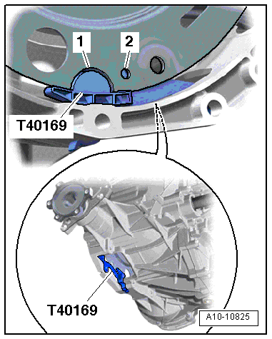
- Insert the -T40169- in the transmission housing and the flywheel from below as shown.
- The assembly aid must engage in the semicircular opening -1- and in the check hole -2-.
Note
There is only one inspection opening on the circumference so rotate the flywheel as needed.
- Install the assembly aid pin into the hole on the transmission housing.
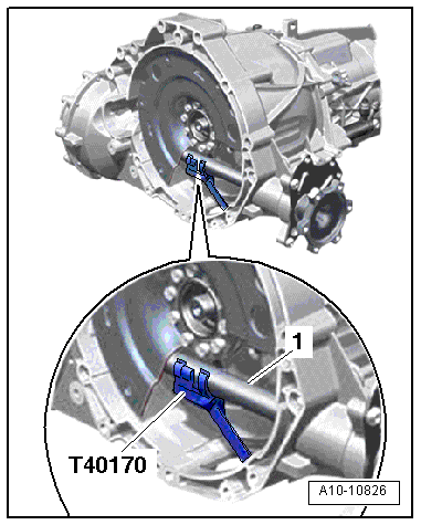
- Insert the -T40170- in the transmission housing from below and secure it on the flange shaft -1-.
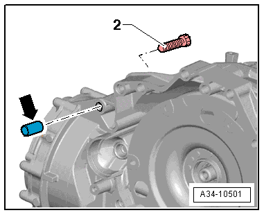
Note
- The bolt -2- attaches the starter to the transmission and has an additional spacer sleeve -arrow-.
- The spacer sleeve must be inserted between the starter and the transmission.
Vehicle with Manual Transmission
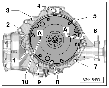
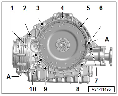
- Check if the alignment sleeves -A- for centering the engine and transmission in the cylinder block are installed.
- Inspect the aluminum bolts used to connect the engine to the transmission to check if they can be used again and mark them if necessary. Refer to → Transmission; Rep. Gr.34; Transmission, Removing and Installing; Transmission Tightening Specifications.
- Position the transmission on the engine and tighten the bolts -3 through 5-. Tightening specifications. Refer to → Transmission; Rep. Gr.34; Transmission, Removing and Installing; Transmission Tightening Specifications.
Vehicle with Dual-Clutch Transmission
- Check if the alignment sleeves -A- for centering the engine and transmission in the cylinder block are installed.
- Inspect the aluminum bolts used to connect the engine to the transmission to check if they can be used again and mark them if necessary. Refer to → Transmission; Rep. Gr.34; Transmission, Removing and Installing; Transmission Tightening Specifications.
- Position the transmission on the engine and tighten the bolts -3 through 5-. Tightening specifications. Refer to → Transmission; Rep. Gr.34; Transmission, Removing and Installing; Transmission Tightening Specifications.
Continuation for All Vehicles
- Release the tension on the -10-222A/11-.
- Lower the workshop crane and mount the engine and transmission onto the engine mount.
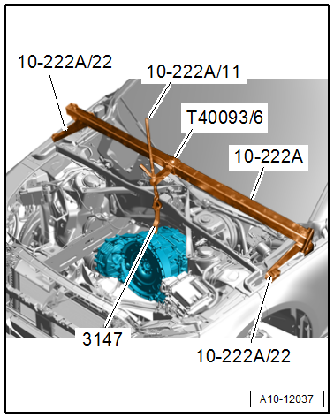
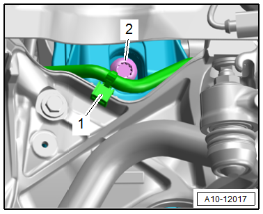
- Tighten the left and right bolts -2- for the engine mount.
Note
Ignore item -1-.
- Remove the -VAS6100- and -2024A-.
Vehicle with Manual Transmission
- Tighten the bolts -6 through 10-. Refer to → Transmission; Rep. Gr.34; Transmission, Removing and Installing; Transmission Tightening Specifications.
Vehicle with Dual-Clutch Transmission
- Tighten the bolts -6 through 10-. Refer to → Transmission; Rep. Gr.34; Transmission, Removing and Installing; Transmission Tightening Specifications.
Continuation for All Vehicles
- Remove the -T40170- and -T40169-.
Note
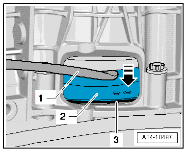
The following procedure is necessary to assure that the flywheel contacts the drive plate evenly and does not get bent.
- Press the flywheel -2- slightly in against the drive plate -3- using an assembly lever -1--arrow-.
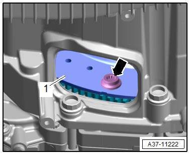
- Secure the flywheel -1- to the drive plate as follows:
Note
Use the -VAG1332/14- to tighten the bolts.
- First install the bolt -arrow- to 10 Nm and then loosen and tighten again to 2 Nm (hand-tight).
 Caution
Risk of destroying the engine by skipping the camshaft timing chain.
Turn the crankshaft only in direction of engine rotation -arrow-.
- Turn the crankshaft with -T40263-, -T40314- and a 24 mm socket 120º in the direction of engine rotation.
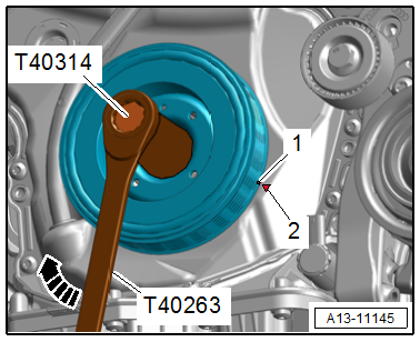
Note
Ignore items -1 and 2-.
- In this crankshaft stub tighten the next bolt. Refer to → Manual Transmission; Rep. Gr.30; Clutch; Overview - Clutch Module or → Direct Shift Gearbox; Rep. Gr.34; Transmission, Removing and Installing; Transmission Tightening Specifications.
- Install the crankshaft 120º in the direction of engine rotation and tighten the next bolt.
- Install the crankshaft 120º in the direction of engine rotation and tighten the last bolt.
Further installation is performed in reverse order of removal, while noting the following:
- Install the starter. Refer to → Electrical Equipment; Rep. Gr.27; Starter; Starter, Removing and Installing.
- Connect the fuel hose. Refer to → Fuel Supply System; Rep. Gr.20; Connector Couplings; Connector Couplings, Disconnecting.
- Install the Heated Oxygen Sensor -G39-. Refer to → Servicing - 4-Cylinder 2.0L 4V TFSI Engine; Rep. Gr.24; Heated Oxygen Sensor; Heated Oxygen Sensor, Removing and Installing.
- Tighten the drive axle. Refer to → Suspension, Wheels, Steering; Rep. Gr.40; Driveshaft; Driveshaft, Removing and Installing.
- Install the drive axle heat shield. Refer to → Suspension, Wheels, Steering; Rep. Gr.40; Driveshaft; Driveshaft Heat Shield, Removing and Installing.
- Install the A/C compressor. Refer to → Heating, Ventilation and Air Conditioning; Rep. Gr.87; A/C Compressor; A/C Compressor, Removing and Installing from Bracket.
- Install the ribbed belt. Refer to → Servicing - 4-Cylinder 2.0L 4V TFSI Engine; Rep. Gr.13; Cylinder Block Belt Pulley Side; Ribbed Belt Tensioner, Removing and Installing.
- Install the air filter housing. Refer to → Chapter "Air Filter Housing, Removing and Installing".
- Connections and wire routing. Refer to → Wiring diagrams, Troubleshooting & Component locations.
- Install the catalytic converter. Refer to → Servicing - 4-Cylinder 2.0L 4V TFSI Engine; Rep. Gr.26; Emissions Control System; Catalytic Converter, Removing and Installing.
- Install the exhaust system without tension. Refer to → Chapter "Exhaust System, Installing without Tension".
- Install the engine cover. Refer to → Servicing - 4-Cylinder 2.0L 4V TFSI Engine; Rep. Gr.10; Engine Cover; Engine Cover, Removing and Installing.
- Fill with engine oil or check the oil level.
- Follow all steps after connecting the battery. Refer to → Electrical Equipment; Rep. Gr.27; Battery; Battery, Disconnecting and Connecting.
Caution
There is a risk of destroying the control modules due to excessive voltage.
Do not use a charger to jump start.
- If the engine is replaced, perform the "01 - mechanical engine, functions" listed adaptation using the Vehicle Diagnostic Tester.
Caution
Risk of component damage.
Perform the additional adaptation for each component, that was replaced at the same time.
- Connect the coolant hose to the connector coupling. Refer to → Fig. "Connect the Coolant Hose to the Connector Coupling".
Note
Used coolant cannot be used again.
- Fill with coolant. Refer to → Chapter "Coolant, Draining and Filling".
- Install the wheel housing liners and wheel spoiler. Refer to → Body Exterior; Rep. Gr.66; Wheel Housing Liner; Overview - Front Wheel Housing Liner.
- Install the front wheels. Refer to → Suspension, Wheels, Steering; Rep. Gr.44; Wheels, Tires.
- Install the noise insulations. Refer to → Body Exterior; Rep. Gr.66; Noise Insulation; Overview - Noise Insulation.
READ NEXT:
 Subframe Mount
Overview - Subframe Mount
Engine Mount
1 - Subframe
2 - Engine Mount
Versions with
Left Electrohydraulic Engine Mount Solenoid Valve -N144-
Right Electrohydraulic Engine Mou
Engine, Supporting in Installation Position
Special tools and workshop equipment required
Engine Support Bridge -10-222A-
Procedure
- Remove the engine cover. Refer to
→ Servicing - 4-Cylinder 2.0L 4V TFSI Engine; Rep. Gr.1
Special Tools
Special tools and workshop equipment required
Locking Pin -T10060A-
Engine Support - Supplement Kit - Adapter -T40093/6- from
the Engine Support - Supplement Kit -T40093A-
Clutch Module Ass
SEE MORE:
Repair Kit for FlexRay Wires with Coating
Note
The repair of FlexRay wires with coating can only take place
using FlexRay wires with coating from the Parts Catalog.
Observe general notes for repairs on the vehicle electrical
system. Refer to
→ Chapter "Vehicle Electrical System, General Repair
Information".
A two-laye
Trailer
Driving with a trailer
General information
Your vehicle is primarily intended for transporting
people and luggage. However, if you drive
with a trailer, follow the technical requirements,
the operation and driving tips, and the legal regulations.
Driving with a trailer affects the vehicle's energy
