Audi A4: Overview - Gear Set
Audi A4 (B9) 2016-2026 Service Manual / Transmission / Servicing - 7-Speed Dual Clutch Transmission 0CJ, 0CL, 0CK / Controls, Housing / Overview - Gear Set
Overview - Gear Set, FWD Vehicles
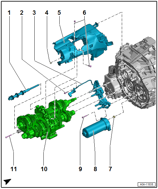
1 - Oil Pipe
2 - Bolt
- 3 Nm + 90Âş
- Replacing
- M6 Ă— 30
3 - Gear Positioner with:
- Transmission Input Speed Sensor 1 -G632-
- Transmission Input Speed Sensor 2 -G612-
- Gear Position Distance Sensor 1 -G487-
- Gear Position Distance Sensor 2 -G488-
- Gear Position Distance Sensor 3 -G489-
- Gear Position Distance Sensor 4 -G490-
- Removing an installing. Refer to → Chapter "Transmission, Disassembling and Assembling".
4 - Seal
- Replacing
5 - Oil Pan
- Replacing
6 - Bolt
- 3 Nm + 90Âş
- Replacing
- M6 Ă— 30
7 - Seal
- Replacing
8 - Hydraulic Pressure Reservoir
- Observe the safety notes. Refer to → Chapter "ATF Pump, Deactivating and Draining the Hydraulic Pump Reservoir".
- Removing an installing. Refer to → Chapter "Transmission, Disassembling and Assembling".
- Disposal. Refer to → Chapter "Hydraulic Pressure Reservoir, Disposing".
9 - Bolts
- 3 Nm + 90Âş
- Replacing
- M6 Ă— 30
10 - Gear Set
- Removing and installing. Refer to → Chapter "Transmission, Disassembling and Assembling".
11 - Bolts
- 6 Nm + 30Âş
- Gearshift rail gear positioner module
- M6 Ă— 50
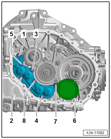
Gear Positioner and Pressure Reservoir Tightening Sequence
 Note
Note
Replace the bolts.
- Tighten the bolts in two steps in the sequence shown:
.png)
Overview - Gear Set, AWD Vehicles
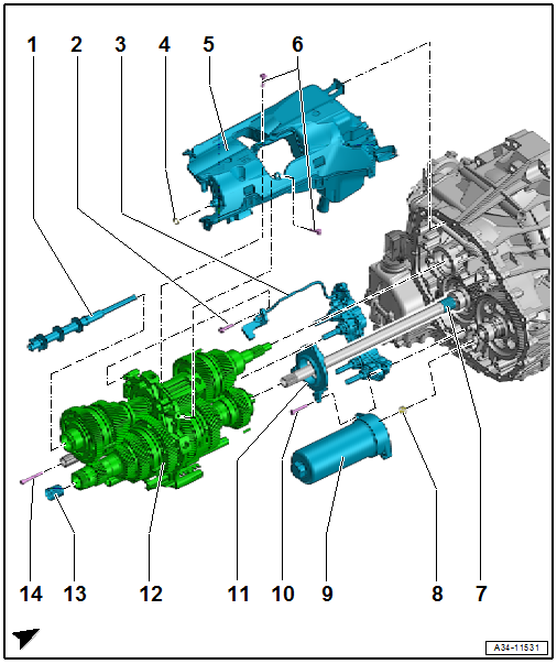
1 - Oil Pipe
2 - Bolt
- 3 Nm + 90Âş
- Replacing
- M6 Ă— 30
3 - Gear Positioner with:
- Transmission Input Speed Sensor 1 -G632-
- Transmission Input Speed Sensor 2 -G612-
- Gear Position Distance Sensor 1 -G487-
- Gear Position Distance Sensor 2 -G488-
- Gear Position Distance Sensor 3 -G489-
- Gear Position Distance Sensor 4 -G490-
- Removing an installing. Refer to → Chapter "Transmission, Disassembling and Assembling".
- Observe the tightening sequence. Refer to → Fig. "Gear Positioner, Pressure Reservoir and Gear Carrier Tightening Sequence".
4 - Seal
- Replacing
5 - Oil Pan
- Replacing
6 - Bolts
- 3 Nm + 90Âş
- Replacing
- M6 Ă— 30
7 - Needle Bearing
8 - Seal
- Replacing
9 - Hydraulic Pressure Reservoir
- Observe the safety notes. Refer to → Chapter "ATF Pump, Deactivating and Draining the Hydraulic Pump Reservoir".
- Removing an installing. Refer to → Chapter "Transmission, Disassembling and Assembling".
- Disposal. Refer to → Chapter "Hydraulic Pressure Reservoir, Disposing".
- Observe the tightening sequence. Refer to → Fig. "Gear Positioner, Pressure Reservoir and Gear Carrier Tightening Sequence".
10 - Bolts
- Replacing
- Observe the tightening sequence. Refer to → Fig. "Gear Positioner, Pressure Reservoir and Gear Carrier Tightening Sequence".
11 - Bearing Bracket with Roller Bearing
- Observe the tightening sequence. Refer to → Fig. "Gear Positioner, Pressure Reservoir and Gear Carrier Tightening Sequence".
12 - Gear Set
- Removing and installing. Refer to → Chapter "Transmission, Disassembling and Assembling".
13 - Needle Bearing
14 - Bolts
- 6 Nm + 30Âş
- Gearshift rail gear positioner module
- M6 Ă— 50
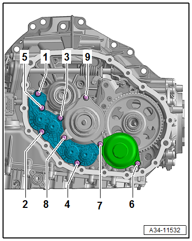
Gear Positioner, Pressure Reservoir and Gear Carrier Tightening Sequence
- Tighten the bolts in four steps in the sequence shown:
.png)
READ NEXT:
 Transmission, Disassembling and Assembling
WARNING
The system is under pressure.
The electronic ATF pump must be deactivated every
time before opening the transmission, and the hydraulic
pressure reservoir is drained.
Refer to
â
Transmission Fluid Circuit
Overview - Transmission Fluid Circuit
1 - Plug
8 Nm +30Âş
Replace after removing.
For the ATF check and fill hole
2 - Plug
35 Nm
Replace after removing.
For transmission
DSG Transmission Mechatronic -J743-
Overview - Mechatronic
1 - Transmission Fluid Pan
Removing and installing. Refer to
→ Chapter "Transmission Fluid Pan, Removing and Installing".
2 - Bolt
Tightenin
SEE MORE:
Rear cross-traffic assist
Description
Applies to: vehicles with rear cross-traffic assist
Fig. 130 Sensor
Fig. 131 Center display: rear cross-traffic assist display
General information
The rear cross-traffic assist monitors the area behind
and next to the vehicle using radar sensors
at the rear corners of the vehicle. T
Wheels and Tires
General information
Check your tires regularly for
damage, such as punctures,
cuts, cracks, and bulges. Remove
foreign objects from the tire
tread.
If driving over curbs or similar
obstacles, drive slowly and approach
the curb at an angle.
Have faulty tires or rims replaced
immediately.
© 2019-2026 Copyright www.audia4b9.com
