Audi A4: Overview - Suspension Strut, Shock Absorber, Spring
Overview - Spring
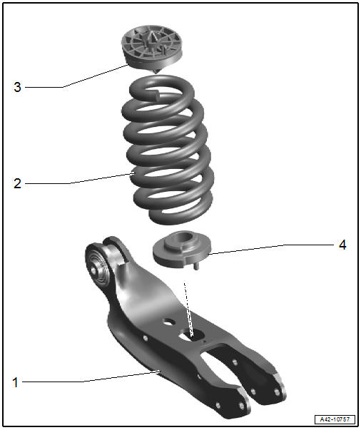
1 - Rear Lower Transverse Link
- Removing and installing. Refer to → Chapter "Rear Lower Transverse Link, Removing and Installing".
2 - Coil Spring
- Removing and installing. Refer to → Chapter "Spring, Removing and Installing".
- Installation position. Refer to → Fig. "Coil Spring and Spring Plate Installation Position".
3 - Upper Spring Support
- Installation position. Refer to → Fig. "Coil Spring and Spring Plate Installation Position".
4 - Lower Spring Support
- Installation position. Refer to → Fig. "Coil Spring and Spring Plate Installation Position".
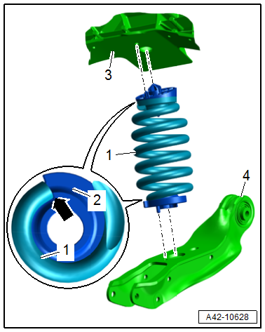
Coil Spring and Spring Plate Installation Position
- The end of the spring -1- must be positioned to the stop on the spring plates -2--arrow-.
- The positioning pins of the spring plate must engage at the top in the holes in the body -3- and at the bottom in the holes in the rear transverse link -4- as shown.
Overview - Shock Absorber
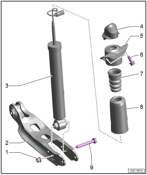
1 - Nut
- 70 Nm + 180º
- Replace after removing
- Tighten in the curb weight position. Refer to → Chapter "Wheel Bearing in Curb Weight Position, Lifting Vehicles with Coil Spring".
2 - Rear Lower Transverse Link
3 - Shock Absorber
- There are different versions. Refer to the Parts Catalog for the allocation.
- Removing and installing. Refer to → Chapter "Shock Absorber, Removing and Installing".
- Vent and discharge faulty shock absorbers before disposal. Refer to → Chapter "Rear Gas-Filled Shock Absorbers, Venting and Draining"
- Shock absorber, checking. Refer to → Chapter "Shock Absorbers, Checking when Removed".
- For equipment versions with electronic damping: "Adapt new control position" using the Vehicle Diagnostic Tester after replacing.
4 - Cover
- For equipment with electronic damping: with wire retainer
5 - Shock Absorber Mount
- Removing and installing. Refer to → Fig. "Shock Absorber Mount, Removing and Installing".
6 - Bolt
- 50 Nm + 90º
- Replace after removing
7 - Additional Spring
8 - Protective Cover
- Installed in the groove on the additional spring
9 - Bolt
- Replace after removing
Shock Absorber Mount, Removing and Installing
- Shock absorber is removed.
Equipment Versions with Electronic Damping:
- Free up the wire on the cover.
- Unlock the contacts and remove the connector housing from the wire. Refer to → Electrical Equipment General Information; Rep. Gr.97; Unlocking and Disassembling from Connector Housings.
- Remove the wiring guide from the nut.
Continuation for All Versions
- Arrange the special tools as shown.
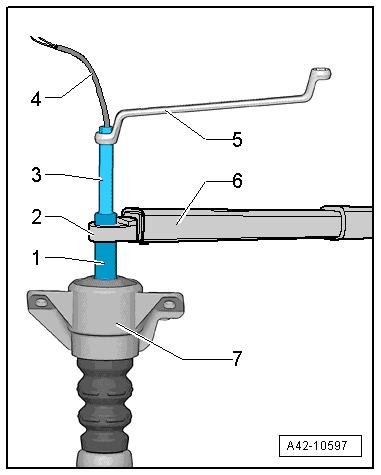
1 - Shock Absorber Set - Socket -T10001/1-
2 - Torque Wrench 1332 Insert - Ring Wrench - 21mm -VAG1332/7-
3 - 8 mm Counterhold-T40279-
4 - Wire
5 - Wrench
6 - Torque Wrench 1331 5-50Nm -VAG1331-
7 - Shock Absorber Mount
Tightening Specifications
- Refer to → Chapter "Overview - Shock Absorber"
READ NEXT:
 Shock Absorber, Removing and Installing
Special tools and workshop equipment required
Torque Wrench 1331 5-50Nm -VAG1331-
Torque Wrench 1332 40-200Nm -VAG1332-
Engine and Gearbox Jack -VAS6931-
Engine/Gearbox Jack Adapter - Wheel Hub S
Spring, Removing and Installing
Special tools and workshop equipment required
Pneumatic/Hydraulic Foot Pump -VAS6179-
Spring Tensioning System -VAS6274-
Spring Tensioning System - Spindle -VAS6274/3-
Spring Tensioning System -
SEE MORE:
Rear Side Window, Removing and Installing
Undamaged Side Window, Removing, Sedan
Special tools and workshop equipment
required
Wedge Set -T10383-
Wedge 1 -T10383/1-
Cutting Tool for Bonded Windows -VAS6452-
Bonded Window Tool Kit - Pull Handle -VAG1351/1-
Follow repair instructions. Refer to
→ Chapter "Repair Information".
To co
Audi connect
Infotainment services
Configuration
Applies to: vehicles with Audi connect Infotainment
Some Audi connect Infotainment services must
be configured through your personal myAudi account
at my.audi.com before using them for the
first time.
Tips
A myAudi user must be logged in for some
Audi connect Infotainment services.
