Audi A4: Radiator, Removing and Installing
Special tools and workshop equipment required
- Coolant Collection System -VAS5014- or Shop Crane - Drip Tray -VAS6208-
- Elbow Assembly Tool -T10118-
 Caution
This procedure contains mandatory replaceable parts. Refer to component overview and parts catalog prior to starting procedure.
Mandatory Replacement Parts
- O-ring - Drain Plug to Coolant Hose
- O-ring - Coolant Line to Radiator
 Note
Note
The radiator is removed and installed together with the fan shroud.
Removing
 WARNING
There is a risk of injury if the radiator fan turns on by itself.
The radiator fans can come on by itself even when the ignition is turned off, such as when heat builds up in the engine compartment.
- Remove the front noise insulation. Refer to → Body Exterior; Rep. Gr.66; Noise Insulation; Noise Insulation, Removing and Installing.
- Remove the bumper cover bracket. Refer to → Body Exterior; Rep. Gr.50; Lock Carrier; Overview - Lock Carrier.
- Place the container of the -VAS5014- or the -VAS6208- underneath.
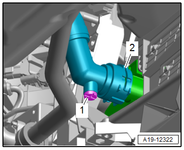
- Pry up the clamp -2- and remove the coolant hose from the lower right of the radiator.
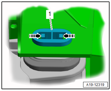
Note
Ignore item -1-.
- Disconnect the radiator fan connector -arrow-.
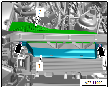
- Release the catches -arrow- and remove the air ducts -1 and 3-.
- Unclip the air duct -2-.
- Remove the bolts -arrows- and air duct -1-.
Note
Ignore item -2-.
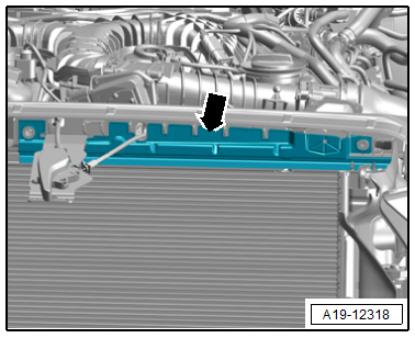
- Remove the upper air duct -arrow-.
- Remove the charge air cooler. Refer to → Chapter "Charge Air Cooler, Removing and Installing".
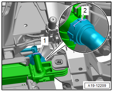
- Disconnect the connector -2- for the High Pressure Sensor -G65-.
Caution
Risk of destroying the radiator.
If the catches are damaged, the radiator must be replaced.
Risk of damaging the refrigerant lines and hoses.
Do not bend, twist or stretch the refrigerant lines and hoses.
- Release the left and right catches -arrows- disengage the condenser -1- from the radiator and tie up to the side.
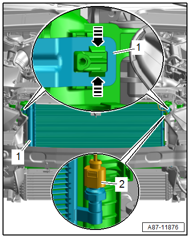
- Lift the clips -1 and 2-, remove the coolant connection from the radiator and free it up.
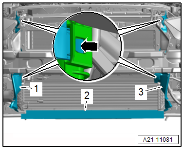
- Remove the left and right bolt -2- and push the radiator bracket -1- with the bolt toward the front -arrow-.
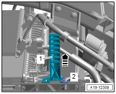
- Release the left and right catches in the direction of -arrows- and remove the retaining pin -1- for the radiator upward.
- Remove the radiator.
- Press the fan shroud left and right locking tabs at the same time in the direction of -arrow- and remove the fan shroud upward from the radiator.
Installing
Install in reverse order of removal and note the following:
Note
If there are small impressions on the slats. Refer to → Servicing - 4-Cylinder 2.0L 4V TFSI Engine; Rep. Gr.00; Repair Information; Radiator and Condenser Assembly.
- Install the charge air cooler. Refer to → Chapter "Charge Air Cooler, Removing and Installing".
- Connections and wire routing. Refer to → Wiring diagrams, Troubleshooting & Component locations.
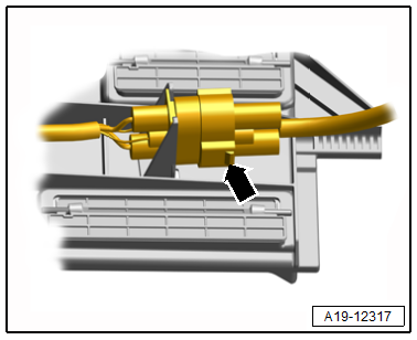
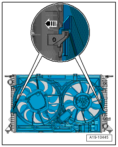
- Connect the coolant hose to the connector coupling. Refer to → Fig. "Connect the Coolant Hose to the Connector Coupling".
Note
Used coolant cannot be used again.
- Fill with coolant. Refer to → Chapter "Coolant, Draining and Filling".
Tightening Specifications
- Refer to → Chapter "Overview - Radiator/Radiator Fan"
- Refer to → Chapter "Overview - Air Filter Housing"
- Refer to → Body Exterior; Rep. Gr.50; Lock Carrier; Overview - Lock Carrier.
- Refer to → Body Exterior; Rep. Gr.66; Noise Insulation; Overview - Noise Insulation.
READ NEXT:
 Fan Shroud, Removing and Installing
Removing
- Remove the front noise insulation. Refer to
→ Body Exterior; Rep. Gr.66; Noise Insulation; Overview - Noise
Insulation.
- Remove the charge air cooler. Refer to
Turbocharger, G-Charger
Turbocharger
All procedures and components are described under:
→ Servicing - 4-Cylinder 2.0L 4V TFSI Engine; Rep. Gr.21; Turbocharger;
Turbocharger, Removing and Installing.
Charge
SEE MORE:
Transmission, Transporting
Special tools and workshop equipment required
Shop Crane -VAS6100-
Lifting Tackle -3033-
Hook And Support Tool -3311- with Hook And Support Tool -
Bolt -3311/1-
Retaining Strap -T40155-
Caution
Risk of damaging the transmission by mixing ATF and
transmission fluid (MTF) through the
Control Module/Digital Sound System Amplifier, Removing and Installing
Special tools and workshop equipment required
Fiber-Optic Repair Set - Connector Protective Caps
-VAS6223/9-.
The Digital Sound System Control Module -J525--1-
is located behind the left luggage compartment side trim panel.
Note
If replacing the control module, select the "Replace contr
