Audi A4: Wheel Bearing Housing, Removing and Installing
Special tools and workshop equipment required
- Spreader Tool -3424-
- Torque Wrench 1332 40-200Nm -VAG1332-
- Engine and Gearbox Jack -VAS6931-
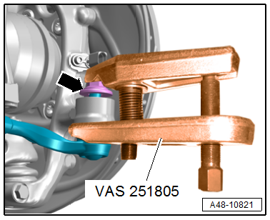
- Ball Joint Splitter -VAS251805-, not illustrated
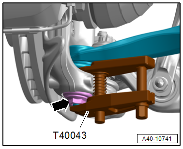
- Puller - Ball Joint -T40043-
 Caution
This procedure contains mandatory replaceable parts. Refer to component overview and parts catalog prior to starting procedure.
Mandatory Replacement Parts
- Bolt - Ball Joint to Wheel Bearing Housing
- Nut - Ball Joint to Control Arm
Removing
- Loosen the connection between the drive axle and wheel hub. Refer to → Chapter "Drive Axle Threaded Connection, Loosening and Tightening".
- Remove the front speed sensor and free up the wire. Refer to → Brake System; Rep. Gr.45; Sensors; Right/Left Front ABS Wheel Speed Sensor G45/G47, Removing and Installing.
- Remove the brake caliper. Refer to → Brake System; Rep. Gr.46; Front Brakes; Brake Caliper, Removing and Installing.
- Remove the bolts -arrows-, and move the bracket -1- to the side.
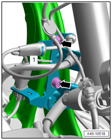
- To protect the threads, remove the nut -arrow- from the tie rod end joint pin until it is flush with the joint pin threads.
 WARNING
There is a risk of injury from falling components.
When pressing off, the tie rod end loosens abruptly from the wheel bearing housing. Use, for example, the -VAS6931- to secure.
Caution
There is a risk of damaging the ball joint puller.
Make sure that both puller lever arms are parallel to each other when using maximum force.
- Remove the tie rod end with the -VAS251805- from the wheel bearing housing.
- Then remove the nut. Use a 6 mm inner hex socket to counterhold at the joint pin if necessary.
- To protect the threads, remove the nut -arrow- on the guide link joint pin until it is flush with the joint pin threads. If necessary counterhold the joint pin.
WARNING
There is a risk of injury from falling components.
When pressing off, the ball joint loosens abruptly from the wheel bearing housing. Use, for example, the -VAS6931- to secure.
- Press out the guide link joint pin with the -T40043- from the conical seat. Do not damage the CV boot while doing so.
- Remove the nut and free up the guide link on the wheel bearing housing. If necessary, counterhold the joint pin with a TX 40 socket to do this.
WARNING
There is an accident risk due to the weight of the wheel bearing housing.
A second technician is required to remove the wheel bearing housing.
Caution
There is a risk of damaging the wheel bearing housing.
The slits in the wheel bearing housing must not be widened using a chisel or similar tool!
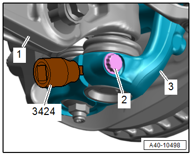
- Disconnect the threaded connection -2-.
- Remove the joint pins for the upper control arm -3- from the wheel bearing housing.
 Note
Note
Ignore items -1 and 4-.
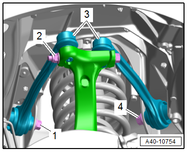
- Remove the bolt -2-.
- Insert the -3424- into the slit on the wheel bearing housing -3- and turn 90º.
- Pull the wheel bearing housing downward from the ball joint and remove it.
- Tie up the drive axle.
Note
- The drive axle must not hang down, otherwise the inner joint will be damaged by over bending.
- Ignore item -1-.
Installing
Install in reverse order of removal and note the following:
- Slide the wheel bearing housing onto the drive axle splines.
- Install the control arm. Refer to → Chapter "Control Arm, Removing and Installing".
- Install the upper control arm. Refer to → Chapter "Upper Control Arm, Removing and Installing".
- Tighten the threaded connection between the drive axle and wheel hub. Refer to → Chapter "Drive Axle Threaded Connection, Loosening and Tightening".
- Overview table for when an axle alignment is needed. Refer to → Chapter "Need for Axle Alignment, Evaluating".
Tightening Specifications
- Refer to → Chapter "Overview - Wheel Bearing"
- Refer to → Chapter "Overview - Lower Control Arm and Ball Joint"
- Refer to → Brake System; Rep. Gr.45; Sensors; Overview - Front Axle Speed Sensor.
READ NEXT:
 Wheel Bearing Unit, Removing and Installing
Special tools and workshop equipment required
Torque Wrench 1332 40-200Nm -VAG1332-
Caution
This procedure contains mandatory replaceable parts.
Refer to component overview and parts cata
Overview - Drive Axle
1 - Clamp
Replace after removing
Tensioning. Refer to
→ Chapter "Clamp on Triple Roller Joint and Outer Joint, Tensioning".
2 - CV Boot
If the drive axle has a peene
SEE MORE:
Suspension Strut, Removing and Installing
Torque Wrench 1331 5-50Nm -VAG1331-
Removing
- Remove the shock absorber fork. Refer to
→ Chapter "Shock Absorber Fork, Removing and Installing".
- Remove the tower brace. Refer to
→ Chapter "Tower Brace, Removing and Installing".
Equipment Versions with Electronic Dampi
Roof Reinforcement, Attaching to Body
Roof Reinforcement, Attaching to Body, Sedan
Special tools and workshop equipment required
Assembly adhesive. Refer to the Parts Catalog.
Procedure
- Remove the headliner. Refer to
→ Chapter "Headliner, Removing and Installing, Sedan".
- Apply adhesive beads -arrows- to
the roo
