Audi A4: Engine, Removing
Special tools and workshop equipment required
- Engine Support Bridge -10-222A-
- Engine Sling -2024A-
- Engine Support Bridge Adapter -3147-
- Ring Wrench 7-Piece Set -3337-
- Torque Wrench 1332 Insert - Ring Wrench - 16mm -VAG1332/14-
- Shop Crane -VAS6100-
- Engine Bung Set -VAS6122-
- Coolant Collection System -VAS5014- or Shop Crane - Drip Tray -VAS6208-
- Hose Clip Pliers -VAS6362-
- Torque Wrench Adapter -VAS6948-
- Locking Pin -T10060A-
- Engine Support - Supplement Kit - Adapter -T40093/6- from the Engine Support - Supplement Kit -T40093A-
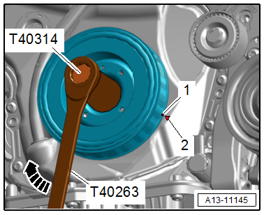
- Wrench - 21mm -T40263-
- Adapter -T40314-
- Engine Support Bridge - Spindle -10-222A/11-
- Engine Support Bridge - Sub-Frame Adapter -10-222A/22-
- Engine Support Bridge Adapter -3147-
Procedure
 Note
Note
- Remove the engine upward without the transmission.
- During installation, all cable ties must be installed at the same location.
 Caution
There is a risk of destroying electronic components when disconnecting the battery.
Follow the steps for disconnecting the battery.
- Disconnect the battery. Refer to → Electrical Equipment; Rep. Gr.27; Battery; Battery, Disconnecting and Connecting.
- On versions with a manual transmission engage the 4th gear.
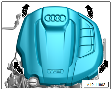
- Carefully pull the engine cover off the retaining pins one after the other in the direction of -arrows-. Do not pull sharply on the engine cover or pull it to one side.
 WARNING
Risk of scalding due to hot coolant.
Pay attention to the safety precautions. Refer to → Servicing - 4-Cylinder 2.0L 4V TFSI Engine; Rep. Gr.00; Safety Instructions; Safety Precautions when Working the Cooling System.
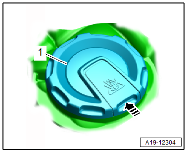
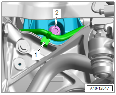
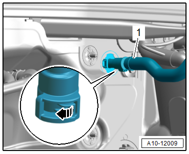
- Open the cover -1- for the coolant expansion tank by releasing the catch in the direction of -arrow-.
- Remove the front wheels. Refer to → Suspension, Wheels, Steering; Rep. Gr.44; Wheels, Tires.
- Remove the noise insulations. Refer to → Body Exterior; Rep. Gr.66; Noise Insulation; Overview - Noise Insulation.
- Remove the left and right wheel spoiler as well as the right front wheel housing liner. Refer to → Body Exterior; Rep. Gr.66; Wheel Housing Liner; Front Wheel Housing Liner, Removing and Installing.
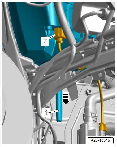
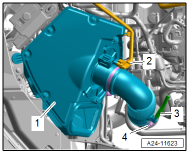
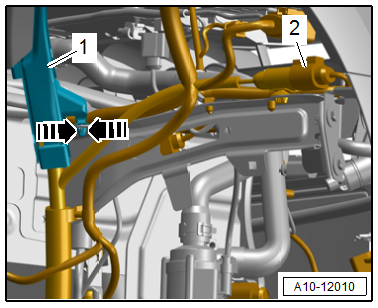
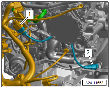
- Equipment version: Disconnect the connector -2- for the Intake Air Switch-Over Valve -N335- and remove the water drain -1- downward in the direction of -arrow-.
- Remove the lock carrier cover. Refer to → Body Exterior; Rep. Gr.63; Front Bumper; Attachments, Removing and Installing.
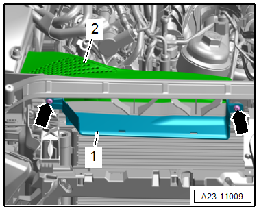
- Remove the bolts -arrows- and the air guide -2-.
Note
Ignore item -1-.
- Disconnect the connector -2- for the Mass Airflow Sensor -G70-.
- Remove the vacuum hose -3-.
- Loosen the hose clamp -4- and remove the air duct hose.
- Pull the air filter housing -1- upward.
- Seal the turbocharger with thoroughly cleaned plugs from the -VAS6122-.
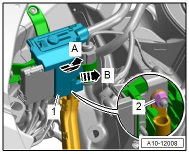
- Release the latch in the direction of -arrow B- and open the E-box -1- in the direction of -arrow A-.
- Remove the nut -2- and free up the B+ wire.
- Free up the upper wiring duct.
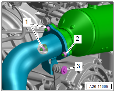
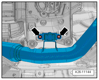
- Remove the nuts -1- from the front muffler accessible from the top.
Note
The nut -2- and bolt -3- will be removed later.
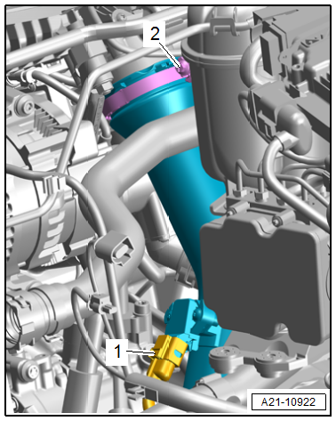
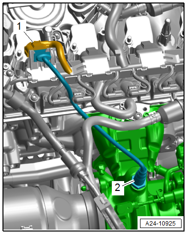
- Disconnect the connector -1- for the Charge Air Pressure Sensor -G31-.
- Loosen the screw-type clamp -2- and remove the air duct pipe from the Throttle Valve Control Module -J338-.
- Place the container of the -VAS5014- or the -VAS6208- underneath.
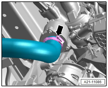
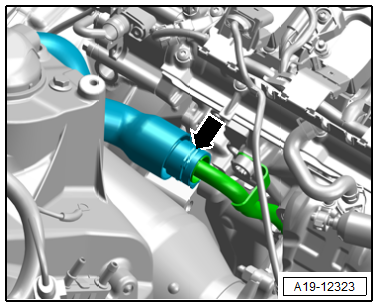
- Open the drain plug -1- on the connection and drain the coolant.
Note
Ignore item -2-.
- Loosen the left front wheel housing liner in the front area and push slightly toward the rear. Refer to → Body Exterior; Rep. Gr.66; Wheel Housing Liner; Overview - Front Wheel Housing Liner.
- Loosen the hose clamp -1- and remove the air duct hose and remove downward.
Note
Ignore the -arrows-.
Note
- Risk of destroying by reversing the running direction on a used ribbed belt.
- Before removing the ribbed belt, mark the running direction with chalk or a felt-tip pen for reinstallation.
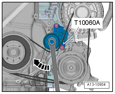
- Turn the tensioner in the direction of -arrow- to release the tension on the ribbed belt.
- Secure the tensioner using the -T10060A-.
- Remove the ribbed belt.
- Remove the A/C compressor from the bracket. Refer to → Heating, Ventilation and Air Conditioning; Rep. Gr.87; A/C Compressor; A/C Compressor, Removing and Installing from Bracket.
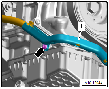
- Remove the bolt -arrow- and remove the wiring duct -1- from the oil pan upper section toward the front and push it downward.
- Loosen the hose clamp -arrow- and remove the air duct hose at the right from the turbocharger.
- Remove the connector -2- from the bracket and disconnect it.
- Release the catches -arrows- and free up the wiring duct -1-.
- Free up the wiring harness to the engine.
- Remove the nut -arrow- and free up the ground wire.
- Remove the bolts -arrows- and remove the right drive axle heat shield.
- Remove the left and right drive axles from the transmission. Refer to → Suspension, Wheels, Steering; Rep. Gr.40; Driveshaft; Driveshaft, Removing and Installing.
- Remove the nut -2- and bolt -3- for the front muffler.
Note
Item -1- not already removed.
Caution
Risk of damaging the couplings in the front muffler.
Do not bend couplings in front muffler more than 10º.
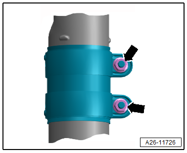
- Remove the bolts -arrows-.
- Loosen the clamping sleeve -arrows- and push toward the rear.
- Remove the front muffler.
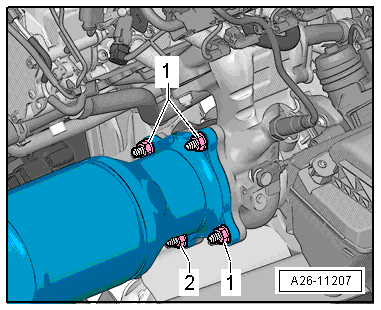
- Remove the catalytic converter nut -2-.
Note
The nuts -1- will be removed later.
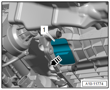
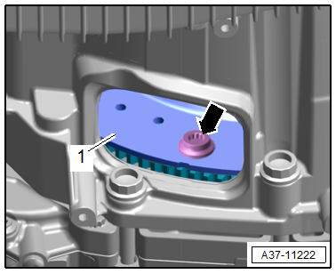
- Remove the lower cover -1- from the transmission in the direction of -arrow-.
- To loosen the bolts for the flywheel, counterhold the crankshaft using the -T40263- and -T40314-.
Caution
Risk of destroying the engine by skipping the camshaft timing chain.
Only turn the crankshaft in the direction of engine rotation.
- Turn the crankshaft an additional 120º respectively in the direction of engine rotation in the direction of -arrow-.
- Remove the three bolts -arrow- for the flywheel -1-.
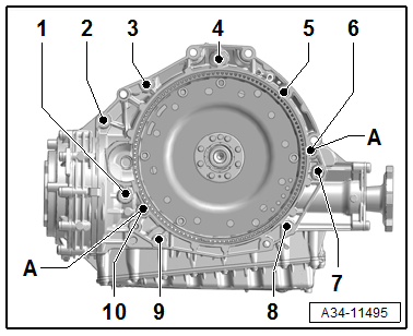
Vehicle with Manual Transmission
- Loosen the bolt -1- with the -VAG1332/14- and -VAS6948-.
- Remove the bolts -6 through 10- that attach the engine to the transmission.
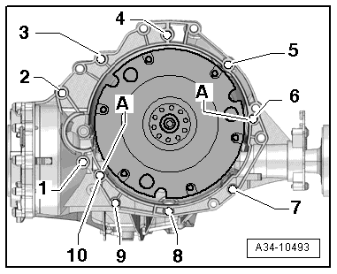
Vehicle with S tronic Transmission
- Loosen the bolt -1- with the - VAG1332/14- and -VAS6948-.
- Remove the bolts -6 through 10- that attach the engine to the transmission.
Continuation for All Vehicles
- Remove the left and right bolt -2- from the engine mount.
Note
Ignore item -1-.
- Disconnect the connector -1- on the Oxygen Sensor After Catalytic Converter -G130--2- and free up the wires. (There are different installation positions.)
- Remove the connector -1- from the bracket and disconnect it.
- Remove the Heated Oxygen Sensor -G39--2- using a tool from the -3337-.
- Remove the nuts -1- and the catalytic converter upward.
Note
Pay attention to the guidelines for clean working conditions. Refer to → Servicing - 4-Cylinder 2.0L 4V TFSI Engine; Rep. Gr.00; Repair Information; Guidelines for Clean Working Conditions.
WARNING
The fuel system is under pressure.
Risk of injury from fuel spraying out.
- Wear protective eyewear.
- Wear safety gloves.
- Reduce the pressure: Place clean cloths around the connection point and carefully open the connection point.
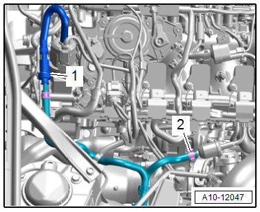
- Remove the fuel hose -1-. Refer to → Fuel Supply System; Rep. Gr.20; Connector Couplings; Connector Couplings, Disconnecting.
- Loosen the hose clamps to disconnect the hose for the EVAP system -2-.
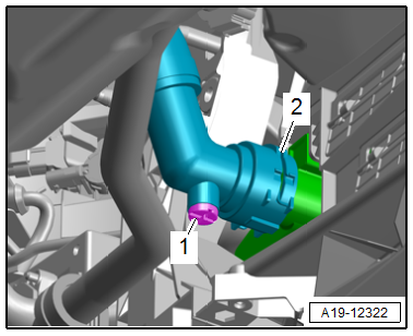
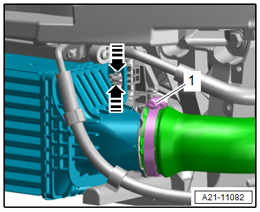
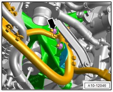
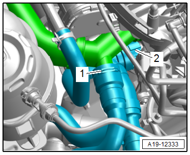
- Lift the clamp -arrow- and remove the coolant hose.
- Lift up the clamps -arrows- and remove and free up the coolant hoses.
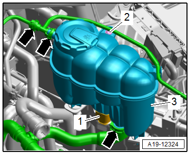
- Disconnect the connector -1- for the Engine Coolant Level Warning Switch -F66-.
- Remove the bolt -2- and remove the coolant expansion tank -3-.
- Lift the clamp -1 and 3-, and remove the coolant hoses.
Vehicle with Dual-Clutch Transmission
- Lift the clamp -2- and remove the coolant hose.
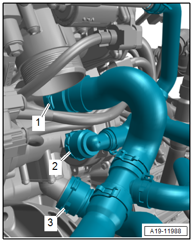
- Loosen the hose clamp -arrow- on the left coolant pipe and remove the coolant hose.
Vehicle with Manual Transmission
- Lift the clamp -1- and remove the coolant hose.
Note
Ignore item -2-.
Continuation for All Vehicles
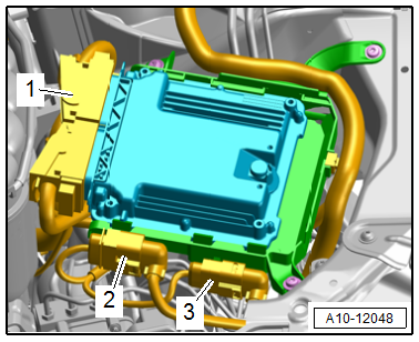
- Remove the connector -2- from the bracket and disconnect it.
- Disconnect the connector -1- from the engine control module.
- Free up the wiring harness and place it on the engine.
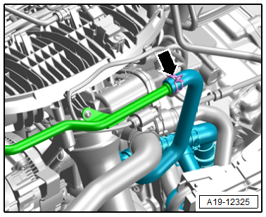
- Release the retainer in the direction of -arrow- and remove the vacuum hose -1-.
Vehicle with Manual Transmission
- Remove -2 to 5- that are accessible from above that connect the engine to the transmission.
- Remove the starter slightly from the transmission and leave it in the installation position.
Vehicle with Dual-Clutch Transmission
- Remove the bolts -2 to 5- that are accessible from above that connect the engine to the transmission.
Continuation for All Vehicles
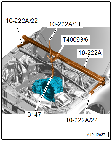
- Position the -10-222A- with -10-222A/22- as shown on the left and right on the fender bolting edge.
- Connect the transmission and the -10-222A/11- with the -3147-.
- Slightly pre-tension the transmission using the spindle.
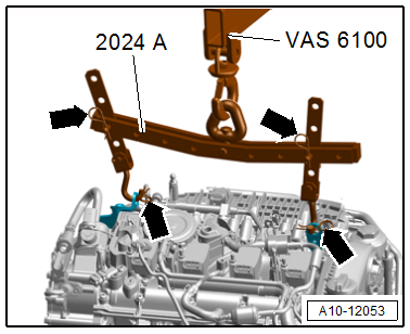
Note
For clarity, the removed engine is shown.
- Engage the -2024A- on the engine and on the -VAS6100- as shown.
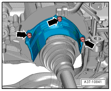
WARNING
There is the risk of an accident.
Lifting hooks and pins on the engine sling must be secured with securing pins -arrows-.
- Lift the engine until the engine mount is free.
- Turn the -10-222A/11-.
Caution
Risk of damaging the hose and line connections as well as the engine compartment.
- Make sure all the hose and line connections between the engine, transmission, subframe and body have been disconnected.
- Carefully lift and guide the engine out of the engine compartment.
- - Remove the engine from the transmission and lift it upward out of the engine compartment.
Engine, Securing to Engine and Transmission Holder
All procedures are described under: → Servicing - 4-Cylinder 2.0L 4V TFSI Engine; Rep. Gr.10; Engine, Removing and Installing; Engine, Securing to Engine and Transmission Holder.
READ NEXT:
 Engine, Installing
Special tools and workshop equipment required
Clutch Module Assembly Aid -T40169-
Clutch Module Transportation Lock -T40170-
as well as when removing with listed special tools
Engine Support Brid
Subframe Mount
Overview - Subframe Mount
Engine Mount
1 - Subframe
2 - Engine Mount
Versions with
Left Electrohydraulic Engine Mount Solenoid Valve -N144-
Right Electrohydraulic Engine Mou
Engine, Supporting in Installation Position
Special tools and workshop equipment required
Engine Support Bridge -10-222A-
Procedure
- Remove the engine cover. Refer to
→ Servicing - 4-Cylinder 2.0L 4V TFSI Engine; Rep. Gr.1
SEE MORE:
Electric Coolant Pump, Removing and Installing
Coolant Recirculation Pump -V50-, Removing and Installing
Special tools and workshop equipment required
Hose Clamps - Up To 25mm -3094-
Hose Clip Pliers -VAS6340-
Removing
- Remove the engine cover. Refer to
→ Servicing - 4-Cylinder 2.0L 4V TFSI Engine; Rep. Gr.10; Engine
Glass Panel, Removing and Installing
Glass Panel, Removing and Installing, Sedan
Caution
This procedure contains mandatory replaceable parts.
Refer to component overview and parts catalog prior to
starting procedure.
Mandatory Replacement Parts
Screw - Glass Panel
The following components must be replaced after removal. R
