Audi A4: Overview - Drive Axle
Audi A4 (B9) 2016-2026 Service Manual / Chassis / Rear Suspension / Drive Axle / Overview - Drive Axle
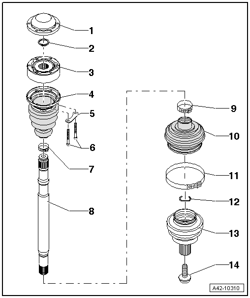
1 - Cap
- Carefully drive off using a drift
- Replace if damaged
- Adhesive surface must be free of oil and grease
- Coat the sealing surface with Sealant -D 454 300 A2- before installing on CV joint.
2 - Circlip
- Replace after removing
- Insert in shaft groove
3 - Inner CV Joint
- Only replace completely
- Checking using the Vehicle Diagnostic Tester. Refer to → Chapter "Inner CV Joint, Checking".
- Grease quantity and type.
- The adhesive surfaces must be free of oil and grease.
- When installing the CV joint, thinly coat the profile shaft splines with the grease used in the joint.
4 - CV Boot
- Without vent hole
- Remove the cap carefully using a drift.
- Check for tears and scuffing
- Check the inner CV joint for damage. Refer to → Chapter "Inner CV Joint, Checking".
- The metal cap/CV joint sealing surfaces must be free of grease when installing.
5 - Backing Plate
6 - Bolts
- M8: 30 Nm +90º
- M10: 50 Nm + 90º
- Replace after removing
7 - Clamp
- Replace after removing
- Tensioning. Refer to → Fig. "Tension the Clamp using the Clamping Pliers -VAG1682A-".
8 - Drive Axle
- Removing and installing. Refer to → Chapter "Drive Axle, Removing and Installing".
9 - Clamp
- Replace after removing
- Tensioning.
10 - CV Boot
- Without vent hole
- Check for tears and scuffing
- Check the outer CV joint for damage. Refer to → Chapter "Outer CV Joint, Checking".
- The outer CV boot/metal cap sealing surfaces must be free of grease when installing
- The CV boot/drive axle sealing surfaces must be free of grease when installing
11 - Clamp
- Replace after removing
- Tensioning. Refer to → Fig. "Tension the Clamp using the Clamping Pliers -VAG1682A-".
12 - Circlip
- Replace after removing
- Insert into ring groove of shaft before installation (not visible on installed joint)
- Before installing the CV joint, align the circlip centered to the opening facing upward.
13 - Outer CV Joint
- Only replace completely
- Checking using the Vehicle Diagnostic Tester. Refer to → Chapter "Outer CV Joint, Checking".
- Removing. Refer to → Chapter "Drive Axle, Disassembling and Assembling, Outer CV Joint".
- Installing: Drive onto shaft with a plastic mallet until compressed circlip rebounds.
- Circlip must lie in joint chamfer when guiding in, guide with pliers if necessary.
- Grease quantity and type.
- The CV boot/outer CV joint sealing surfaces must be free of grease when installing.
- When installing the CV joint, thinly coat the profile shaft splines with the grease used in the joint.
14 - Bolt
- Replace after removing
- Clean the threads in the CV joint with a thread tap.
- Drive axle threaded connection, loosening and tightening. Refer to → Chapter "Drive Axle Threaded Connection, Loosening and Tightening".
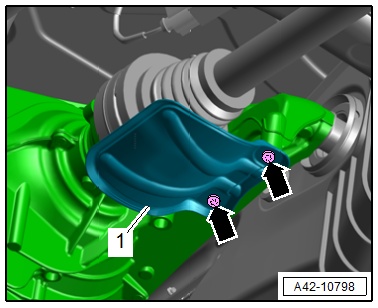
Heat Shield - Tightening Specification
- Tighten the heat shield bolts to 23 Nm.
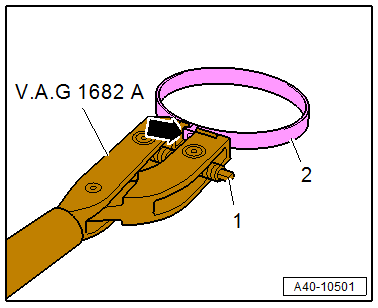
Tension the Clamp using the Clamping Pliers -VAG1682A-.
- Attach the Clamping Pliers -VAG1682- as shown.
- The jaws on the pliers must be centered -arrow- on the clamp -2-.
 Note
Note
- The spindle threads must turn easily. If necessary, coat with MoS2 lubricating grease.
- If difficult to tighten, for example because of dirty threads, the proper clamping force of the clamping sleeve will not be reached even when tightened to the specification.
- Tension the clamp by turning the spindle -1- with the torque wrench. Do not tilt the clamping pliers during this.
- Tightening specification: 20 Nm.
Grease Quantity and Type
Note
- Grease the joint again when replacing the CV boot.
- Pay attention to the grease type for the outer and inner joint. Refer to the Parts Catalog.
.png)
1) Apply grease through the ball races.
READ NEXT:
 Drive Axle, Removing and Installing
Caution
This procedure contains mandatory replaceable parts.
Refer to component overview and parts catalog prior to
starting procedure.
Mandatory Replacement Parts
Bolt - Outer CV Joint t
Drive Axle, Disassembling and Assembling
Drive Axle, Disassembling and Assembling, Outer CV Joint
Special tools and workshop equipment required
Locking ring pliers, commercially available
Sealant -D454 300 A2-. Refer to the Parts Catalog.
Inner CV Joint, Checking
It is necessary to disassemble the joint whenever replacing
the grease or if the ball surfaces show wear or damage.
Disassembling
Note
Ball hub and joint are paired and should be identified
SEE MORE:
Engine oil
If the engine oil level too low
If you need to add engine oil, use an oil that is listed on the sticker. The
sticker is located at the front of the engine compartment fig. 158. When using
the engine oil listed on the sticker, you can adjust the oil level as often as
needed.
If engine oil that mee
Transmission Fluid Pan, Removing and Installing
Special tools and workshop equipment required
Engine Bung Set -VAS6122-
Used Oil Collection and Extraction Unit -SMN372500-
Removing
Note
General repair instructions. Refer to
→ Chapter "Repair Information".
Guidelines for clean working conditions when working on the
dual-clu
© 2019-2026 Copyright www.audia4b9.com
