Audi A4: Steering Column, Checking for Damage
Visual Check
- Components of the steering column must not show any indications of damage.
Function Test
- The steering column must turn without catching or difficulty of movement.
- The steering column must adjust easily from side to side and vertically (this test is only possible when installed).
Steering Column, Handling and Transporting
 WARNING
Damages to the steering column creates a safety risk.
The steering column must always be handled correctly.
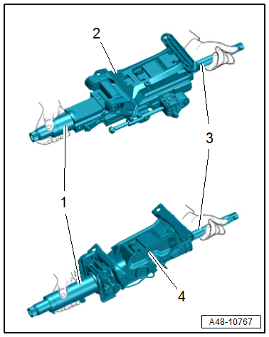
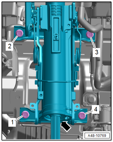
Correct Handling and Transport of Steering Column
2 - Power Adjustable Steering Column
4 - Manual Adjustable Steering Column
- Transport steering column using two hands.
- Hold the steering column at the upper column tube -1- and in the stub shaft area -3- on the upper universal joint.
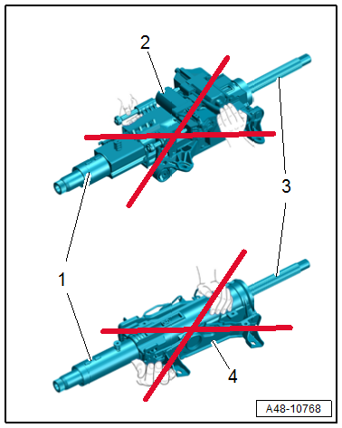
Incorrect Handling of Steering Column
Transporting the following components can cause damage to the steering column and can lead to serious personal injury
- Power adjustable steering column -2-: Motor, spindles, connectors and wiring harness
- Manual adjustable steering column -4-: Release lever and weight balancing springs
The steering column must not have any mechanical load:
- A steering column that has fallen onto a hard surface or shows signs of damage must not be installed in the vehicle.
- Do not lay the steering column on the stub shafts -1 and 3-.
- The stub shafts must not get compressed.
Steering Column, Removing and Installing
Special tools and workshop equipment required
- Torque Wrench 1331 5-50Nm -VAG1331-
- Bolt Extractor Set -VAS5514-
- Protector Set -VAS871009-
Also for equipment versions with anti-theft protection component:
- Steering column repair kit. Refer to the Parts Catalog
- -VAS5514-, not illustrated
- -VAS871009-, not illustrated
- Hand drill
- 4.5 mm drill bit
- Protective Eyewear
 Caution
This procedure contains mandatory replaceable parts. Refer to component overview and parts catalog prior to starting procedure.
Mandatory Replacement Parts
- Bolt - Steering wheel to Steering Column
Removing
- Remove the driver side footwell cover front section. Refer to → Body Interior; Rep. Gr.68; Storage Compartments and Covers; Driver Side Instrument Panel Cover, Removing and Installing.
- Remove the driver side footwell vent. Refer to → Heating, Ventilation and Air Conditioning; Rep. Gr.87; Air Guide; Driver Side Footwell Vent, Removing and Installing.
- Remove the steering column switch module. Refer to → Electrical Equipment; Rep. Gr.94; Steering Column Switch Module; Steering Column Switch Module, Removing and Installing.
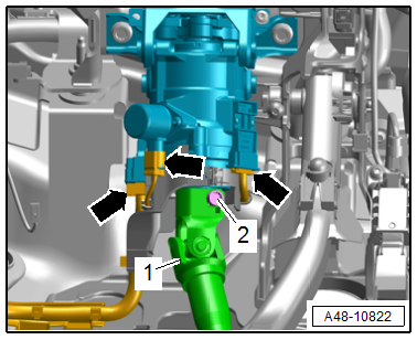
- Remove the bolt -2- and remove the steering intermediate shaft universal joint -1- from the active steering actuator/steering column.
- Equipment with active steering: disconnect the connectors -arrows- and free up the wires by removing the wire bracket.
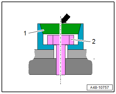
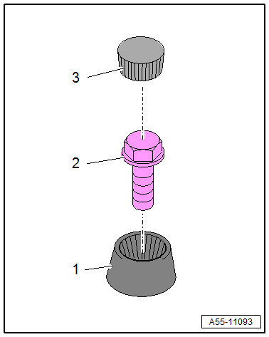
Equipment Versions With Anti-Theft Protection Component
- Insert the -VAS871009-.
Caution
Wear protective eyewear for all of the following procedures.
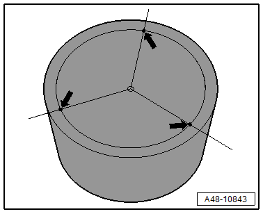
- Punch the anti-theft protection three times into the groove for the upper and lower section tilted at 120º. This ensures that the upper piece of the anti-theft protection component -1- does not turn when drilling.
- Punch the upper section of the anti-theft protection component -1- in the center and drill through with a carbide 4.5 mm drill bit from the repair kit.
- Drill the bolt -2- approximately 8 mm through the drill hole -arrow- in the upper section of the anti-theft protection component -1- using a commercially available 4.5 mm drill bit.
- Drill through the upper section of the anti-theft protection component -1- with a carbide 7.0 mm drill bit from the repair kit.
- Remove the bolt with anti-theft protection using screwdriver no. 4 from the -VAS5514-.
- Vacuum up drill shavings.
Continuation for All Vehicles
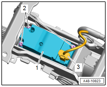
- Remove the bolts in the sequence -4 to 1- while supporting the steering column -arrow- from below by hand.
- Disengage the steering column toward the rear and lower slightly.
- Disconnect and free up the connector -3- for the Electronic Steering Column Lock Control Module -J764--1-.
 Note
Note
Ignore item -2-.
- Remove the steering column.
- Disconnect the steering column from the active steering actuator. Refer to → Chapter "Steering Column, Disconnecting from Active Steering Actuator".
Installing
Install in reverse order of removal and note the following:
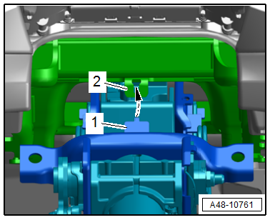
- Bring the steering column into the installation position by engaging the mounting hooks -1- on the central tube -2--arrow-.
Equipment Versions with Anti-Theft Protection Component
- Bring the bolt -2- with the anti-theft protection component lower section -1- into the installation position.
- Tighten the bolts. Refer to → Fig. "Steering Column - Tightening Specification and Sequence".
- Drive the anti-theft protection component upper section -3- flush into the lower section using a plastic mallet.
- Install the steering intermediate shaft. Refer to → Chapter "Steering Intermediate Shaft, Removing and Installing".
- Readapting the end position of the steering gear. Refer to → Chapter "Steering Gear End Positions, Adapting".
- Calibrate the Steering Angle Sensor -G85-. Refer to → Chapter "Steering Angle Sensor -G85- Basic Setting".
Tightening Specifications
- Refer to → Chapter "Overview - Steering Column"
READ NEXT:
 Active Steering Safety Lock (Locking Solenoid), Removing and Installing
Special tools and workshop equipment required
Vehicle Diagnostic Tester
Torque Wrench 1783 - 2-10Nm -VAG1783-
Removing
Note
To avoid a crooked steering wheel, the steering wheel must
no
Electronic Steering Column Lock Control Module -J764-, Removing and
Installing
Special tools and workshop equipment required
Torque Wrench 1783 - 2-10Nm -VAG1783-
Removing
- Remove the steering column from the instrument panel central
tube and place in the driver footwe
SEE MORE:
Test Sequence
Battery, Checking, Vehicles with Battery Monitoring Control Module J367
or Energy Management Control Module J644 and Data Bus On Board Diagnostic
Interface J533
In certain model series the following is responsible for
monitoring the electrical system: Energy Management Control
Module -J644- or
Rear Door Trim Panel, Removing and Installing
Special tools and workshop equipment required
Wedge Set -T10383-
Wedge Set - Wedge 1 -T10383/1-
Removing
- Switch off the ignition.
- Unclip the decorative trim -1-
using the -T10383/1- in the direction of
-arrow A-.
- Release the remaining retainers, disengage the decorative tr
