Audi A4: Underbody Trim Panel
Audi A4 (B9) 2016-2026 Service Manual / Body / Body Exterior / Exterior Equipment / Underbody Trim Panel
Overview - Underbody Trim Panels
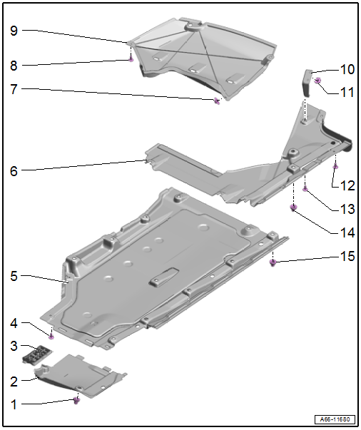
1 - Nut
- 2 Nm
- Quantity: 2
2 - Front Underbody Panel
- Removing and installing. Refer to → Chapter "Underbody Trim Panel, Removing and Installing, Front".
3 - Impact Protector
4 - Bolt
- 2 Nm
5 - Center Underbody Trim Panel
- Removing and installing. Refer to → Chapter "Underbody Trim Panel, Removing and Installing, Center".
6 - Rear Underbody Trim Panel
- Removing and installing. Refer to → Chapter "Underbody Trim Panel, Removing and Installing, Rear".
7 - Nut
- 2 Nm
- Quantity: 2
8 - Bolt
- 2 Nm
- Quantity: 3
9 - Side Underbody Trim Panel
- Removing and installing. Refer to → Chapter "Underbody Trim Panel, Removing and Installing, Side".
10 - Bracket
- For the rear underbody trim panel
11 - Nut
- 2 Nm
12 - Bolt
- 2 Nm
13 - Bolt
- 2 Nm
- Quantity: 2
14 - Nut
- 2 Nm
- With fastener
- Quantity: 2
15 - Nut
- 2 Nm
- With fastener
- Quantity: 11
Overview - Underbody Bracing
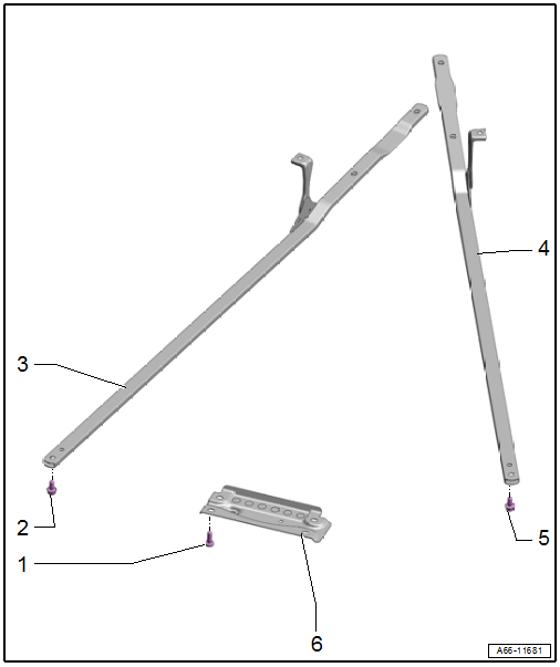
1 - Bolt
- 55 Nm
- Quantity: 4
2 - Bolt
- 50 Nm + 90º
- Replace after removing
- Quantity: 5
3 - Right Diagonal Brace
- Removing and installing. Refer to → Chapter "Diagonal Braces, Removing and Installing".
4 - Left Diagonal Brace
- Removing and installing. Refer to → Chapter "Diagonal Braces, Removing and Installing".
5 - Bolt
- 50 Nm + 90º
- Replace after removing
- Quantity: 5
6 - Tunnel Brace
- Removing and installing. Refer to → Chapter "Tunnel Brace, Removing and Installing".
READ NEXT:
 Underbody Trim Panels, Removing and Installing
Underbody Trim Panel, Removing and Installing, Front
Removing
- Remove the nuts -arrows-.
- Remove the front underbody trim panel -2-
from the center underbody trim panel -1-.
Installing
Roof Molding/Roof Railing
Overview - Roof Railing
1 -
Nut
Quantity: 4
Insert with locking fluid. Refer to the Parts Catalog.
Tightening specification and sequence. Refer to
→ Fig. "Roof Railing - Tightening
Exterior Rearview Mirror
Overview - Exterior Rearview Mirror
1 -
Mirror Trim
2 -
Bolt
1.5 Nm
3 -
Mirror Adjusting Unit
Removing and installing. Refer to
→ Chapter "Mirror Adjusting
SEE MORE:
General Information
High pressure side are the condenser, receiver/dryer and
restrictor or expansion valve to separate the high and low
pressure liquid ends.
High pressure results from the restrictor or expansion valve
forming a constriction and causing the refrigerant to
accumulate, thus leading to an increase in
Tachometer
The tachometer (1) displays the engine
speed in revolutions per minute (RPM). The beginning
of the red zone in the tachometer indicates
the maximum permissible engine speed for
all gears once the engine has been broken in. Before
reaching the red zone, you should shift into
the next higher gear, sel
© 2019-2026 Copyright www.audia4b9.com
