Audi A4: Windshield Antenna Suppression Filter -C18-, Removing and Installing
Windshield Antenna Suppression Filter -C18-, Removing and Installing, Sedan
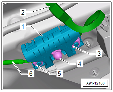
The Windshield Antenna Suppression Filter -C18- is located behind the left D-pillar trim panel at the center of the D-pillar.
Removing
- Turn off the ignition and all electrical equipment and remove the ignition key.
- Remove the left D-pillar trim panel. Refer to → Body Interior; Rep. Gr.70; Vehicle Interior Trim Panels; D-Pillar Trim Panel, Removing and Installing.
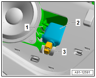
- Remove the nuts -3 and 5- on the Windshield Antenna Suppression Filter -C18--1-.
- Disconnect the wires -2 and 6- on the Windshield Antenna Suppression Filter -C18--1-.
- Remove the nut -4- and then remove the Windshield Antenna Suppression Filter -C18--1- from the D-pillar.
Installing
- Install in reverse order of removal. Note the following:
Tightening Specifications
- Refer to → Chapter "Component Location Overview - Antenna Systems, Sedan, USA"
- Refer to → Chapter "Component Location Overview - Antenna Systems, Sedan, Europe and Rest of World"
Windshield Antenna Suppression Filter -C18-, Removing and Installing, Avant
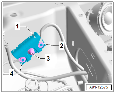
The Windshield Antenna Suppression Filter -C18- is located in the left front of the luggage compartment behind the luggage compartment side trim panel.
Removing
- Turn off the ignition and all electrical equipment and remove the ignition key.
- Remove the left luggage compartment side trim panel. Refer to → Body Interior; Rep. Gr.70; Luggage Compartment Trim Panels; Luggage Compartment Side Trim Panel, Removing and Installing.
- Remove the nuts -2 and 4- on the Windshield Antenna Suppression Filter -C18--1-.
- Disconnect the wires on the Windshield Antenna Suppression Filter -C18--1-.
- Remove the nut -3- and the Windshield Antenna Suppression Filter -C18--1-.
Installing
- Install in reverse order of removal. Note the following:
Tightening Specifications
- Refer to → Chapter "Component Location Overview - Antenna Systems, Avant, USA"
- Refer to → Chapter "Component Location Overview - Antenna Systems, Avant, Europe and Rest of World"
Traffic Data Antenna, Removing and Installing
The Traffic Data Antenna -R173- is located at the top of the windshield on the left side (only ER5).
Removing
- Turn off the ignition and all electrical equipment and remove the ignition key.
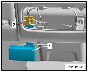
The connectors -2- for the Traffic Data Antenna -R173--1- are located on the roof crossmember, behind the left sun visor. The flat band cable -2- is routed on the roof crossmember.
- Disconnect the connector -2-.
Traffic Data Antenna -R173- removal:
A safety piece -2- secures the Traffic Data Antenna -R173--1- to its bracket -3-. The bracket is glued to the windshield -3-.
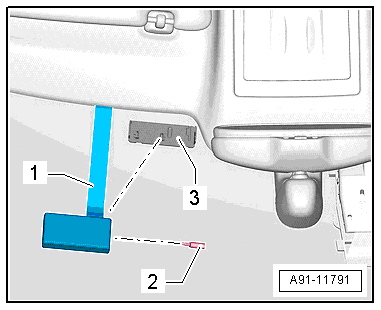
- Remove the safety piece -2- with a small screwdriver.
- Remove the Traffic Data Antenna -R173--1- from the bracket -3-.
Installing
- Installation is identical in reverse order of removal.
Close Range Communication Antenna, Removing and Installing
The Close Range Communication Antenna -R269- is located in the center of the front instrument panel (only ER5).
Removing
- Turn off the ignition and all electrical equipment and remove the ignition key.
- Remove the center defroster vent with the speaker trim. Refer to → Body Interior; Rep. Gr.70; Instrument Panel; Center Front Defroster Vent, Removing and Installing.
- Release the retainers -1-.
- Tilt the Close Range Communication Antenna -R269--2- out of the retainer in the instrument panel.
- Release and disconnect the connector -3-.
Installing
- Installation is identical in reverse order of removal.
READ NEXT:
 Emergency Module Antenna, Removing and Installing
Emergency Module Antenna -R263-, Removing and Installing, Vehicles
without Tinted Glass
The Emergency Module Antenna -R263- is located in the front
center instrument panel (only IW3)
Removing
-
Overview - Telephone
Overview - Telephone, Bluetooth Hands-Free
Calling, 9ZX
The Information Electronics Control Module 1 -J794- is
installed with the Microphone Unit In Front Roof Module -R164-
and is exclusively for
SEE MORE:
Fuse assignment - footwell
Fig. 183 Driver's footwell (left-hand drive vehicle): fuse
panel with plastic clip
Fig. 184 Front passenger's footwell (right-hand drive vehicle):
fuse panel with plastic clip
Fuse panel (A) (brown)
Catalytic converter heating
Engine components
Exhaust doors, fuel injectors, air intake,
motor
Water Drain Hoses
Overview - Water Drain Hoses
Overview - Front Water Drain Hoses
1 -
Grommet
Push all the way into the body using a soap solution
2 -
Front Water Drain Hose
Cleaning. Refer to
→ Chapter "Water Drain Hoses, Cleaning".
Removing and installing. Refer to
→ Chapte
