Audi A4: Transmission Tightening Specifications
 Note
Note
- The tightening specifications apply only to lightly greased, oiled, phosphated or blackened nuts and bolts.
- Additional lubricants, such as engine oil or transmission fluid are permitted, but lubricants containing graphite are not.
- Do not use any ungreased parts.
- Tightening specification tolerance: +- 15%.
- Drive plate flywheel. Refer to → Servicing - 7-Speed Dual Clutch Transmission 0CJ, 0CK, 0CL; Rep. Gr.30; Clutch; Overview - Flywheel and Dual Clutch.
- Assembly mounts. Refer to → Chapter "Overview - Subframe Mount".
Transmission to 4-Cylinder FSI Engine:
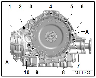
.png)
- 1) Mount the auxiliary adapter
- 2) Bolt strength rating 10.9. There is no limit to the number of times steel bolts may be used.
- 4) The bolts may be used twice.
Transmission on 4-Cylinder TDI Engine:
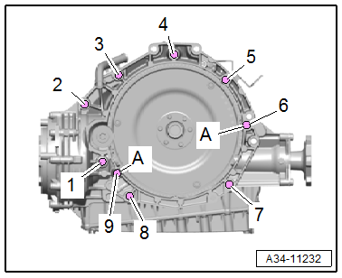
.png)
- 1) Mount the auxiliary adapter
- 2) Bolt strength rating 10.9. There is no limit to the number of times steel bolts may be used.
- 3) also secures that starter; with an additional spacer sleeve between the starter and the transmission.
- 4) The bolts may be used twice.
Transmission to 6-Cylinder TDI Engine:
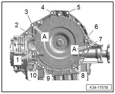
.png)
- 1) Mount the auxiliary adapter
- 2) Bolt strength rating 10.9. There is no limit to the number of times steel bolts may be used.
- 4) The bolts may be used twice.
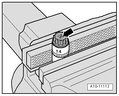
The aluminum bolts -2 through 10- can be used twice. Therefore, the bolts must be marked with two notches "X" made by a chisel after they have be used the first time -arrow-.
To prevent damaging the bolts when marking them, do not clamp them in a vise. Insert the bolt in a 14 mm socket with a 1/2 drive, which is inserted in to the vise, as shown.
Bolts marked with an "X" may not be used again.
Transmission, Transporting
Description of the Procedure. Refer to → Servicing - 7-Speed Dual Clutch Transmission 0CJ, 0CK, 0CL; Rep. Gr.34; Transmission, Transporting.
Securing on Engine and Transmission Holder
Description of the Procedure. Refer to → Servicing - 7-Speed Dual Clutch Transmission 0CJ, 0CK, 0CL; Rep. Gr.34; Securing on Engine and Transmission Holder.
READ NEXT:
 Subframe Mount
Overview - Subframe Mount
1 - Bolt
70 Nm for FWD vehicles (M10x40 10.9)
40 Nm +90Âş for AWD vehicles (M10x40 8.8)
2 - Tunnel Crossmember
Removing and installing. Refer to
â
Transmission Fluid Circuit
Overview - Transmission Fluid Circuit
1 - Plug/Plugs
For the ATF check and fill hole -item 1-
→ Item
2 - Plug
35 Nm
Replace after removing
For the transmission flui
ATF Circuit
Overview - ATF Circuit
Caution
Risk of damaging the transmission.
Remove all the plugs on the ATF lines and on the
transmission that were installed during removal.
The ATF cooling functio
SEE MORE:
Roof Molding/Roof Railing
Overview - Roof Railing
1 -
Nut
Quantity: 4
Insert with locking fluid. Refer to the Parts Catalog.
Tightening specification and sequence. Refer to
→ Fig. "Roof Railing - Tightening Specification and Sequence".
2 -
O-Ring
Replace if damaged
3 -
Lifter
0.5
Visual Inspection
WARNING
Risk of injury. Follow all warning messages and
safety precautions. Refer to
→ Chapter "Warnings and Safety Precautions".
Before any extensive measurements are taken, visually
inspect the exterior of the battery, the connections, and the
secure installation of the Battery
